BGA solder joint inspection is a crucial quality control process that involves visual and X-ray examination of solder joints. Its primary purpose is to ensure the high quality and reliability of these joints. The inspection helps identify various defects such as cold solder joints, bridging defects, voiding defects, and solder balling defects.
However, due to the intricate nature and irregular shape of solder joints, visual inspection alone is challenging and insufficient. Consequently, this article aims to highlight the effectiveness of X-ray imaging as a preferred method for BGA solder joint inspection.
Now, let us delve into an exploration of the common BGA inspection methods before understanding why X-ray imaging stands out as a highly effective approach.
Some Common Methods Used to Inspect a BGA Solder Joint
Inspecting a Ball Grid Array (BGA) solder joint can be a technical and complicated task because the solder balls are not directly visible. It requires specialized equipment and trained personnel to accurately assess the quality of the joint. Here are some common methods used to inspect a BGA solder joint:
1. X-Ray Inspection
X-ray inspection is the most common method used for inspecting BGA solder joints. This non-destructive testing method can detect soldering defects like solder bridges, voids, or missing balls.
There are two types of X-ray systems: 2D and 3D.
● 2D X-Ray: This method provides a top-down view of the BGA, which can be useful for identifying gross defects. However, it may not reveal problems with individual balls that are hidden by others.
● 3D X-Ray (CT Scan): This method provides a three-dimensional view of the BGA, allowing for a more detailed inspection. This can reveal defects that may not be visible in a 2D X-ray.
2. Acoustic Micro Imaging (AMI)
AMI uses ultrasound technology to inspect solder joints. The ultrasound waves can penetrate the package and reflect back to create an image of the joints. This can reveal voids, cracks, and delaminations that may not be visible using X-ray inspection.
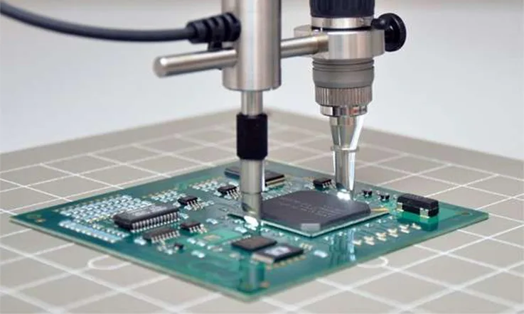
3. Endoscopic Inspection
Endoscopic inspection involves using a small camera to visually inspect the solder joints. This method can reveal defects on the surface of the solder balls, but it doesn’t provide information about the interior of the joints.
4. Destructive Testing
In some cases, it may be necessary to use destructive testing methods to inspect BGA solder joints. This could involve de-soldering the BGA and inspecting the individual solder balls. While this method can provide detailed information about the joints, it destroys the BGA in the process and is typically used for failure analysis rather than routine inspection.
Remember, each of these methods has its strengths and weaknesses, and the best approach often involves using a combination of them. It is also important to have trained personnel conduct these inspections to ensure accurate results.
What is a BGA X Ray Machine?
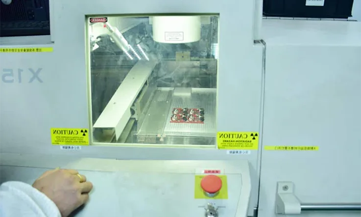
A BGA X-ray machine, also known as a BGA X-ray inspection system or BGA X-ray system, is a specialized equipment used for the inspection and analysis of Ball Grid Array (BGA) solder joints. It employs X-ray imaging technology to provide detailed and non-destructive visualization of the internal structures and connections within BGA packages.
The BGA X-ray machine typically consists of the following key components:
X-ray Source: It generates X-ray radiation that passes through the BGA package and is detected on the other side. The X-ray source can be a microfocus X-ray tube or a more advanced technology like a sealed X-ray tube or an X-ray generator.
Detector: The X-ray detector captures the X-ray radiation that passes through the BGA package. It may utilize technologies such as phosphor screens, flat-panel detectors, or complementary metal-oxide-semiconductor (CMOS) sensors. The detector converts the X-ray radiation into visible images or digital signals for analysis.
Control System: This system manages and controls the operation of the BGA X-ray machine. It includes software interfaces, user controls, and settings for adjusting X-ray parameters such as voltage, current, exposure time, and image capture settings.
Manipulation Mechanism: The BGA X-ray machine may have a motorized stage or a manipulator that allows precise positioning and rotation of the BGA package during the inspection process. This enables capturing X-ray images from different angles and viewpoints.
Imaging and Analysis Software: The software associated with the BGA X-ray machine provides tools for image acquisition, enhancement, measurement, and analysis. It allows operators to examine the X-ray images, identify potential defects or anomalies in the solder joints, and make informed decisions based on the inspection results.
The BGA X-ray machine is specifically designed to address the challenges of inspecting BGA solder joints, which are hidden beneath the package and not easily visible through traditional visual inspection methods. It enables thorough examination of solder quality, joint integrity, voiding, bridging, and other potential defects, helping to ensure the reliability and quality of electronic assemblies that utilize BGA components.
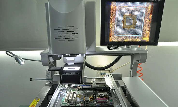
BGA X ray Machine Working Principle
A BGA X-ray machine works by utilizing X-ray imaging technology to penetrate the Ball Grid Array (BGA) package and capture detailed images of the internal structures and solder joints. The process can be summarized in the following steps:
Preparation: The BGA package to be inspected is prepared by ensuring it is properly positioned and securely held in place within the X-ray machine. This may involve using a manipulator or motorized stage to achieve precise alignment for accurate imaging.
X-ray Generation: The X-ray machine produces X-ray radiation using an X-ray source, which is typically a microfocus X-ray tube. The X-ray source emits a controlled beam of X-rays towards the BGA package.
X-ray Penetration: The X-ray beam passes through the BGA package, interacting with the materials it encounters, including the solder joints, substrate, and other internal components. The X-rays can penetrate the package due to the different absorption rates of the materials.
X-ray Detection: On the opposite side of the BGA package, there is an X-ray detector. The detector captures the X-rays that have passed through the package. The detector can be a phosphor screen, a flat-panel detector, or a CMOS sensor, depending on the specific X-ray machine.
Image Conversion: The X-ray detector converts the captured X-rays into visible images or digital signals. Phosphor screens emit visible light when exposed to X-rays, which can be captured using a camera. Flat-panel detectors and CMOS sensors directly convert X-rays into digital signals.
Image Analysis: The captured X-ray images or digital signals are processed and analyzed using specialized software associated with the X-ray machine. The software provides tools for image enhancement, measurement, and analysis. Operators can examine the images to identify potential defects or anomalies in the solder joints, such as voids, bridging, or insufficient solder.
Inspection and Evaluation: Based on the analysis results, operators can make informed decisions regarding the quality and reliability of the solder joints. They can determine if the solder joints meet the required standards or if any further actions, such as rework or repair, are necessary.
The BGA X-ray machine’s ability to penetrate the package and provide internal imaging enables comprehensive inspection of the solder joints, which are otherwise hidden from view. This non-destructive inspection method helps ensure the integrity and reliability of electronic assemblies that incorporate BGA components.
Which is the Best Method for the Inspection of a Solder Joint?
There is no universally superior method for BGA inspection, as each approach possesses its own advantages and disadvantages. The selection of a suitable method depends on the specific defects to be detected and the type of solder joints under inspection.
For instance, if the objective is to identify defects such as solder voids or closed circuits, visual inspection proves to be a viable method. Visual inspection allows for direct observation of the solder joints, enabling detection of surface-level irregularities.
When considering the use of an X-ray machine for BGA inspection, it is essential to understand the various types of defects that can be detected through this method. X-ray machines are primarily employed to identify voiding defects, wherein excess solder is not adequately deposited on the substrate. This specific defect type can only be accurately detected using X-ray imaging.
In addition to voiding defects, X-ray machines can also identify other solder joint issues such as cold solder joints and bridging defects. Cold solder joints occur when the solder paste does not receive sufficient heat or pressure during the soldering process. While infrared cameras can also detect this defect, an X-ray machine can be utilized for its identification as well.
Bridging defects, on the other hand, manifest when the solder paste extends between the package and the board or when it spans across dual-side copper. Similar to cold solder joints, infrared cameras can be employed to identify bridging defects, but an X-ray machine can also effectively detect this type of defect.
To determine when it is appropriate to use an X-ray machine for BGA inspection, it is crucial to have a comprehensive understanding of its functioning. This knowledge enables better decision-making regarding the optimal timing for utilizing the X-ray machine in the inspection process. By maximizing the utilization of the device, unnecessary expenditures in terms of time and resources can be avoided.
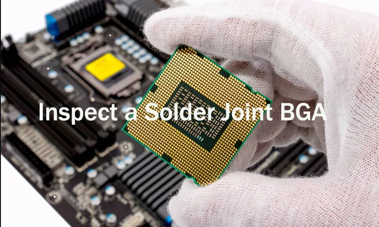
Inspect a Solder Joint BGA Steps
To perform BGA X-ray inspection, the process typically involves the following steps:
Equipment Setup: Begin by selecting a suitable X-ray machine and placing it on the worktable. The BGA board to be inspected is positioned on the X-ray table and securely fixed in place, often using a blanket or other securing methods. Ensure the X-ray machine is switched on and ready for operation.
Alignment: The BGA board should be positioned perpendicular to the X-ray source to ensure accurate imaging. Proper alignment helps achieve clear and precise X-ray images for analysis.
Image Capture: Press the “take picture” button or initiate the imaging process using the X-ray machine’s control panel. This action captures an X-ray image of the BGA solder joints.
Analysis of Solder Joints: The X-ray images obtained are subjected to analysis using dedicated image processing software. The software allows for quantitative analysis of solder joints, including counting the number of solder balls and measuring spacing. This data is then used to calculate metrics such as the percentage of missing balls, spacing, and spacing differences.
Detection of Missing Balls: By examining the X-ray images, operators can identify any gaps in the solder joints, indicating missing solder balls. Air within the void space appears as radiolucent material. The number of gaps observed corresponds to the number of missing solder balls in that joint.
Detection of Bridging Defects: X-ray image analysis can also reveal the presence of bridging defects. These defects manifest as gaps between solder balls, positioned above the substrate’s surface. The bridging defect appears as an abnormally bright spot in the X-ray image. When observed under a microscope, bridging defects disrupt the dome-shaped formation of the solder ball’s top surface.
Detection of Voiding Defects: Voiding defects, another type of solder joint defect, are identified through X-ray image analysis. These defects appear as abnormally bright spots in the X-ray image. The radiolucent material within the void space may consist of air or solder paste. The presence of air indicates the presence of a voiding defect.
By following these steps and utilizing the image analysis method outlined above, BGA X-ray inspection allows for comprehensive evaluation of solder joints, enabling the detection of missing balls, bridging defects, and voiding defects. This analysis aids in maintaining the quality and reliability of BGA assemblies.