
Rogers PCBs are the real deal when it comes to high-frequency circuit boards, made from top-notch materials sourced exclusively from the Rogers Corporation. These laminates are the go-to choice for high-speed applications, commercial microwave systems, and radio frequency domains. What makes Rogers materials stand out is their killer dielectric constant and thermal stability, blowing standard FR4 materials out of the water. Plus, the low water absorption feature of Rogers laminates makes them perfect for high-humidity situations.
If you’re on the lookout for the best bang for your buck on Rogers PCBs, JarnisTech has got your back. We’re here to help you navigate the fabrication process and manufacturing the perfect PCB circuits Boards for your projects. As an official Rogers PCB manufacturer, we’re committed to giving you the best prices while ensuring you get top-shelf Rogers PCBs that meet the highest standards.
Don’t wait around—reach out to us today for a chat or to kickstart your next project. At JarnisTech, we’re all about making your ideas come to life!
What are Rogers PCBs?
Overview of Rogers Materials
Rogers PCBs are crafted using high-performance materials specifically designed for applications requiring exceptional thermal stability and low dielectric loss. Unlike traditional FR-4, which is commonly used in standard PCBs, Rogers materials, such as Rogers 4350B and Rogers 5880, are engineered to excel in extreme conditions, making them the go-to choice for RF (radio frequency) and microwave applications.
Rogers materials stand out due to their impressive dielectric constant (Dk) stability across a broad frequency spectrum, which helps maintain signal integrity in high-speed circuits. They also boast significantly better thermal conductivity than FR-4, allowing them to dissipate heat like a pro, making them a go-to choice for high-power applications. This combo of properties means they’re a solid pick for any demanding electronic design.
| Material | Dielectric Constant (Dk) | Thermal Conductivity (W/m·K) | Typical Applications |
| Rogers 4350B | 3.48 | 0.65 | RF circuits, microwave antennas |
| Rogers 5880 | 2.2 | 1.0 | High-frequency amplifiers, radars |
| FR-4 | 4.5 | 0.3 | General-purpose electronics |
Applications in Telecommunications and Aerospace
The robust characteristics of Rogers PCBs make them indispensable in the telecommunications sector. These boards are a big deal for ensuring that signals are transmitted efficiently—nobody likes a dropped call! In satellite communications, where signal loss can lead to critical failures, Rogers PCBs help to keep things crystal clear, making sure that messages get through loud and proud.
In the aerospace industry, the reliability of components is non-negotiable. Rogers PCBs find their way into various applications, from avionics systems to radar technology. They handle extreme temperatures and vibrations like pros, ensuring consistent performance. For instance, advanced navigation systems depend on these boards to facilitate high-frequency operations required for precise location tracking and data processing. When you’re flying at high altitudes, you want your gear to be rock solid.
As technology continues to push boundaries, the demand for lightweight and efficient materials grows. Rogers PCBs are here to answer the call, providing solid performance without adding unnecessary weight—something aerospace engineers are always keeping an eye on.
So, if you’re looking to elevate your designs and push the envelope in your projects, Rogers PCBs are the way to go. They’re not just another option; they’re a game plan for success in applications where performance truly matters.
Common Types of Rogers PCB Laminates
Rogers Corporation offers a smorgasbord of laminate materials, each designed to tackle specific application needs. Let’s break down some of the most popular laminate series, highlighting their unique properties and real-world applications.
RO4000® Series
The RO4000® Series is the crème de la crème of hydrocarbon-based laminates, delivering outstanding high-frequency performance. This series shines in telecommunications and aerospace, boasting low loss and solid thermal stability.
RO4003C: A fan favorite for its sweet spot between cost and performance, perfect for various RF applications.
RO4350B: This ceramic-filled hydrocarbon resin laminate is a low-loss wonder, enhancing signal integrity where it counts.
RO4360: Designed for high thermal conductivity, this lightweight champ is a go-to for demanding conditions.
RO4835: Another powerhouse for high-frequency applications, this laminate excels under pressure.
Example:
Recently, an aerospace company leveraged RO4350B for a radar system. They found that the laminate cut signal loss significantly, proving that picking the right material can really take your project to the next level.
RO3000® Series
The RO3000® Series features ceramic-filled hydrocarbon resin, a cost-effective choice without skimping on performance.
RO3003: This reliable laminate hits the sweet spot for high-frequency applications while keeping costs in check.
RO3006: Perfect for environments where temperatures swing, this laminate brings thermal stability to the table.
RO3010: A solid player for multilayer designs, it balances performance and affordability like a pro.
Table of RO3000 Series Laminates
| Laminate | Dielectric Constant | Loss Factor | Application |
| RO3003 | Moderate | Low | General RF applications |
| RO3006 | Moderate | Low | High-temperature settings |
| RO3010 | Moderate | Moderate | Multilayer designs |
RT/duroid® Series
The RT/duroid® Series is where the magic happens with PTFE (Teflon) and ceramic fillers, making it ideal for ultra-low loss and high-frequency applications, especially in RF and microwave fields.
RT/duroid 5880: This laminate is a superstar for thermal stability and low dielectric loss—perfect for high-frequency microwave circuits.
RT/duroid 6002: A go-to for automotive radar systems, thanks to its rock-solid reliability in varied conditions.
RT/duroid 6006: This option thrives in extreme thermal environments, making it a favorite for military applications.
RT/duroid 6010LM: Specifically designed for low-loss microwave applications, it delivers stellar signal integrity.
RO5000® Series
The RO5000® Series features modified epoxy laminates that are halogen-free and designed for high-frequency use with low loss.
RO5870: A solid choice for high-speed digital applications, this laminate keeps signal integrity in check.
RO5880: With great thermal stability, it’s a dependable option for demanding environments.
Other Laminates
ULTRALAM® 3000 Series: Flexible and designed for multilayer and microstrip configurations, these modified epoxy laminates are versatile for various applications.
RO2800 Series: Cost-effective and reliable, this series offers glass-reinforced hydrocarbon laminates for less demanding projects.
TMM® Series: With tight control over dielectric constants, these ceramic-filled laminates are perfect for high-precision RF applications.
So, Picking the right laminate can make or break your Rogers PCB project. With so many options out there, engineers can find the perfect match for their specific needs. So whether you’re working in aerospace, telecommunications, or automotive, there’s a Rogers laminate ready to get the job done right. Don’t just take my word for it—dive in and explore what fits your needs best!
How to Choose the Right Rogers PCB Laminates?
 Rogers 4350B PCB
Selecting the right laminate for your Rogers PCB isn’t a cakewalk, but getting it dialed in can really make a difference in performance. Let’s take a closer look at what to consider and share some recommendations for specific applications that’ll set you up for success.
Factors to Consider in Laminate Selection
When picking a laminate, keep the following key factors in mind:
Frequency Range: Different applications demand different frequency capabilities. High-frequency applications often call for low-loss laminates like the RO4000® Series. If you’re working with RF signals, you want materials that won’t let your signal fade away.
Thermal Stability: If your PCB will face extreme temperatures, look for laminates that can handle the heat. RT/duroid® Series laminates are a solid choice here, known for their robust thermal performance.
Dielectric Constant (Dk): The dielectric constant affects signal speed and integrity. A lower Dk is preferable for high-frequency applications. For instance, if you’re designing for 5G, the RO4350B could be your best bet due to its controlled Dk.
Loss Factor: The loss factor indicates how much signal loss occurs in the laminate. For high-performance applications, aim for laminates with a low loss factor, such as those found in the RO4000® Series.
Cost: While it’s tempting to go for the top-tier laminates, budget constraints often come into play. The RO3000® Series offers a good balance of performance and cost-effectiveness.
Recommendations for Specific Applications
Here’s a quick rundown of laminate recommendations based on common applications:
| Application | Recommended Laminate | Key Features |
| RF and Microwave | RT/duroid 5880 | Ultra-low loss, high-frequency performance |
| Telecommunications | RO4350B | Low-loss, excellent thermal stability |
| Automotive Radar | RT/duroid 6002 | Reliable in varied temperature conditions |
| High-Speed Digital Designs | RO5870 | Good thermal stability and signal integrity |
| General RF Applications | RO3003 | Cost-effective with moderate performance |
Sum up, Choosing the right Rogers PCB laminate isn’t just a checklist; it’s about understanding your specific needs and the environment in which your board will operate. By weighing the factors mentioned and referring to the recommendations, you’ll be well on your way to finding the perfect laminate that meets your project’s demands. So don’t just wing it—take a good look at your options and make an informed choice!
What Factors Should You Be Thinking About When Designing the Rogers PCB?
Essential Design Considerations
When you’re diving into Rogers PCB design, a few factors can really turn the tide for your project. We’re looking at layer count, copper thickness, dielectric constant, and more. Let’s break it down so you can knock it out of the park, especially for high-frequency applications.
Layer Count: layer count matters. The more layers you add, the more complex your circuitry can get. But don’t bite off more than you can chew—too many layers can lead to signal integrity issues and bloated manufacturing costs. For example, a six-layer Rogers PCB can pack a punch by supporting intricate designs and minimizing electromagnetic interference (EMI). Just keep in mind, balancing complexity and cost is the name of the game!
Copper Thickness: Next up is copper thickness. It’s not just about how thick you want it; it’s about how that thickness influences current handling and thermal performance. Ranging from 1 oz to 3 oz per square foot, thicker copper layers can manage higher currents and dissipate heat like a pro. For instance, in RF applications where the power can fluctuate, going with 2 oz copper can keep things cool and reliable.
| Design Factor | Considerations | Impact on Performance |
| Layer Count | Balancing complexity and cost | Affects routing, EMI, and manufacturing costs |
| Copper Thickness | Ranges from 1 oz to 3 oz | Influences current handling and heat dissipation |
| Dielectric Constant | Lower values reduce signal loss | Critical for maintaining signal integrity |
Dielectric Constant: Now let’s talk dielectric constant. This factor is your golden ticket to better performance in high-frequency applications. Rogers materials typically have lower dielectric constants than FR-4, leading to less signal loss and a smoother journey for your signals. Take Rogers 4350B, for instance, with a dielectric constant around 3.48. This choice is a slam dunk for applications like 5G, where maintaining signal integrity over long distances is a must.
Real-World Application: Here’s where it gets interesting: picture a company working on a high-frequency radar system. They went with a multi-layer Rogers PCB featuring a low dielectric constant and 2 oz copper. This combo was a real winner, helping them nail signal integrity while keeping heat management on point. The outcome? A product that not only met performance specs but also stayed within budget.
Thermal Management: And let’s talk thermal management! In high-frequency designs, keeping your components cool is no joke. Using thermal vias or heat sinks can really help out, making sure everything stays within safe temperature ranges. So don’t overlook this—it can really turn the tide on performance!
In a nutshell, designing a Rogers PCB is all about juggling multiple factors like layer count, copper thickness, and dielectric constant. Keep these in mind, and you’ll be well on your way to creating a board that meets the high demands of today’s tech. So roll up your sleeves and get into the nitty-gritty—your design’s success is just around the corner!
Types of Rogers PCB Fabrication
Standard Rogers PCB Fabrication Techniques
Rogers PCB fabrication employs several standard methods that ensure high precision and performance, particularly in high-frequency applications. Two of the most common techniques are laser drilling and photolithography. These methods help deliver accuracy and reliability, making sure your designs hit the mark in demanding environments.
Laser Drilling: This technique allows for the creation of microvias, which are small holes that enable inter-layer connections in multi-layer boards. With microvias, you can pack more circuits into a smaller space, optimizing circuit density without skimping on performance. For example, in a recent project for a telecommunications company, the use of laser drilling allowed the design team to achieve a 50% increase in routing density, significantly enhancing the board’s capabilities.
Photolithography: This method involves coating the PCB substrate with a light-sensitive material, then exposing it to UV light through a mask that defines the circuit pattern. The exposed areas are then developed and etched away, creating precise circuit pathways. This technique is like the bread and butter of PCB fabrication, ensuring that the boards meet tight tolerances necessary for high-frequency signals. For instance, in aerospace applications, where every millimeter counts, photolithography helps maintain the integrity of complex designs.
| Fabrication Technique | Description | Key Benefits |
| Laser Drilling | Creates microvias for inter-layer connections | Increases routing density, optimizes performance |
| Photolithography | Utilizes light-sensitive materials for patterning | Ensures precise circuit pathways, maintains tolerances |
Advanced Rogers PCB Fabrication Techniques
As the industry continues to evolve, advanced techniques are shaking things up in Rogers PCB fabrication. One notable method is additive manufacturing, which is carving out a niche in the PCB world.
Additive Manufacturing: This technique builds up the PCB layer by layer, using materials such as conductive inks. This method not only slashes waste but also offers unparalleled design flexibility. Engineers can experiment with complex geometries and integrate components directly into the substrate, which can lead to more innovative designs. For instance, a tech startup recently used additive manufacturing to create a flexible Rogers PCB that could bend without losing performance, allowing for new applications in wearable technology.
Another innovative technique is direct write technology, which allows for the deposition of conductive materials directly onto the substrate without the need for traditional etching. This opens the door to rapid prototyping, enabling engineers to bring ideas to life faster than ever.
| Advanced Technique | Description | Key Advantages |
| Additive Manufacturing | Builds PCBs layer by layer using conductive inks | Reduces waste, enhances design flexibility |
| Direct Write Technology | Deposits conductive materials directly on the substrate | Speeds up prototyping, allows for complex designs |
Overview of Rogers PCB Fabrication Process
 Rogers 5880 PCB
The fabrication process of Rogers PCBs is a meticulous journey that comprises several key stages: design, material selection, fabrication, and testing. Each step is instrumental in crafting a final product that meets the demanding standards of high-frequency applications.
Design: The design phase sets the foundation for the entire fabrication process. Engineers use advanced CAD software to create detailed schematics and layouts that consider factors like signal integrity and layer stackup. This is where creativity meets precision; a well-thought-out design can make all the difference. For example, a recent project involving RF amplifiers required careful layout to minimize signal loss, leading to a design that was both innovative and efficient.
Material Selection: Selecting the right materials is a game plan that directly impacts performance. Rogers materials, such as Rogers 4350B or Rogers 5880, are chosen for their superior dielectric properties and thermal stability. This choice is not just about picking a name off the shelf; it’s about finding the right fit for specific applications. For instance, when a defense contractor needed a PCB that could withstand harsh environments, they opted for a Rogers substrate that provided the necessary durability.
Fabrication: Once the design and materials are locked in, it’s time to hit the production floor. The fabrication process typically involves techniques such as laser drilling and photolithography, ensuring that the boards are made with high precision. For example, a recent fabrication run utilized laser drilling to create microvias that allowed for denser routing, proving that when it comes to Rogers PCBs, every little detail counts.
Testing: Testing is where everything comes together. Before the final product hits the market, it undergoes rigorous testing to ensure it meets all specifications. This phase includes electrical testing, thermal cycling, and mechanical stress tests. A telecommunications firm once discovered during testing that a minor design tweak could enhance signal performance by 15%, showcasing the importance of this stage in the overall process.
| Stage | Description | Key Considerations |
| Design | Create detailed schematics and layouts | Signal integrity, layer stackup |
| Material Selection | Choose appropriate Rogers materials | Dielectric properties, thermal stability |
| Fabrication | Utilize advanced techniques for production | Precision, techniques like laser drilling |
| Testing | Conduct rigorous tests on the final product | Electrical, thermal, and mechanical tests |
Custom Solutions in Rogers PCB Fabrication
Tailored fabrication solutions can be a lifesaver for businesses facing unique challenges. Whether it’s custom stackups or specialized materials, having the right solution can make or break a project. For instance, a telecommunications company was on the hunt for a low-loss substrate for their 5G infrastructure. By collaborating closely with their fabrication partner, they developed a custom stackup that optimized signal integrity, ultimately improving performance across their network.
This kind of customization isn’t just about checking boxes; it’s about pushing the boundaries of what’s possible. Custom solutions allow companies to tackle specific needs, whether they require enhanced thermal management or specific impedance characteristics.
| Customization Aspect | Description | Example |
| Custom Stackups | Tailored layer arrangements for performance | A 5G infrastructure project using low-loss substrates |
| Specialized Materials | Materials chosen for unique requirements | High-frequency applications needing specific Dk values |
Cost Considerations in Rogers PCB Fabrication
Budgeting for Rogers PCB fabrication involves a careful examination of various factors. It’s not just about the upfront costs of materials; it’s about considering manufacturing processes, testing, and potential overruns. Conducting a thorough cost analysis can prevent unwelcome surprises down the line.
For example, a manufacturer might initially underestimate the cost of advanced testing procedures. However, understanding these costs upfront allows for better resource allocation and helps avoid project delays. When planning a budget, businesses should account for material costs, labor, and the expenses associated with quality assurance.
| Cost Factor | Description | Impact on Budget |
| Material Costs | Expenses related to Rogers substrates | Direct impact on overall fabrication costs |
| Manufacturing Processes | Costs associated with different fabrication methods | Varies based on technique used |
| Testing | Expenses incurred during quality assurance | Essential for product reliability |
Pure Rogers PCB vs. Hybrid Rogers PCB
When it comes to picking the right PCB for your project, understanding the differences between Pure Rogers and Hybrid Rogers PCBs can really make a difference. Let’s break down the performance and application differences, along with some tips on when to go with each type. This knowledge can help you make the best choice for your needs.
Performance and Application Differences
Pure Rogers PCBs:
Pure Rogers PCBs are crafted exclusively from Rogers materials, such as the RO4000® and RO3000® Series. These boards excel in high-frequency applications due to their superior thermal stability and low loss.
Key Features:
●High Thermal Stability
●Low Signal Loss
●Consistency
Applications:
●Aerospace and Defense
●Telecommunications
Hybrid Rogers PCBs
Hybrid Rogers PCBs combine Rogers materials with traditional substrates like FR-4. This blend aims to balance performance with cost-effectiveness.
Key Features:
●Cost-Effective
●Versatile Applications
●Improved Design Flexibility
Applications:
●Consumer Electronics
●Automotive
Guidelines on When to Use Each Type
| PCB Type | Best Use Cases | When to Avoid |
| Pure Rogers PCB | High-frequency, high-reliability applications | Budget-constrained projects |
| Hybrid Rogers PCB | Cost-sensitive applications with moderate performance | Critical systems where performance cannot be compromised |
Example: A telecommunications firm was gearing up to launch a new antenna for urban 5G deployment. Given the high-frequency demands and reliability required, they opted for a Pure Rogers PCB to ensure minimal signal loss. On the flip side, a consumer electronics company creating a new smart device chose a Hybrid Rogers PCB to keep costs down while still offering solid performance.
In a words, Choosing between Pure and Hybrid Rogers PCBs boils down to understanding your specific project requirements. If you need top-notch performance and reliability, Pure Rogers is the way to go. But if you’re looking to save a few bucks without sacrificing too much on performance, Hybrid might be your best bet. So, assess your needs carefully and pick the type that aligns with your project goals!
Comparison of Nanya PCB, Nelco PCB, Isola PCB, and Rogers PCB
Material Properties and Applications
When it comes to PCBs, you’ve got options, but let’s cut to the chase: Rogers PCB is often the go-to choice for high-performance applications. Here’s the lowdown on how it stacks up against the likes of Nanya, Nelco, and Isola.
Nanya PCB: Known for their affordability, Nanya offers reliable solutions that are perfect for basic applications. They’re like the dependable friend who’s always there but might not have the flashiest skills.
Nelco PCB: These guys are all about versatility. With a solid lineup of materials, they cater to a wide range of industries. If you need something that can adapt like a chameleon, Nelco’s your buddy.
Isola PCB: A heavyweight in the game, Isola provides high-tech materials that excel in complex designs. They’re the innovators in the crowd, pushing the boundaries of what’s possible.
Rogers PCB: Here’s where the rubber meets the road. Rogers specializes in materials that shine in high-frequency applications, making them a heavyweight contender for RF and microwave designs.
Key Advantages and Applications of Rogers PCB Compared to Others
Thermal Stability: They handle heat like a champ, maintaining performance under stress. This makes them a hit in aerospace and telecommunications.
Dielectric Properties: The low loss and high dielectric constant of Rogers materials allow for efficient signal transmission. It’s like having a clear line of communication without any static.
Custom Solutions: Need something tailored? Rogers has you covered with custom stackups that optimize signal integrity for specific applications.
Summary Table: Comparison of Key Features
| Feature | Nanya PCB | Nelco PCB | Isola PCB | Rogers PCB |
| Cost | Low | Moderate | High | Moderate-High |
| Thermal Stability | Good | Good | Excellent | Excellent |
| Dielectric Properties | Moderate | Good | Excellent | Superior |
| Application Suitability | Basic | Versatile | Complex Designs | High-Frequency |
Importance of Quality in Rogers PCB Assembly
 Rogers 4003C PCB
Quality Standards and Certifications
In Rogers PCB assembly, quality truly takes center stage. Following recognized quality standards isn’t just about ticking boxes; it’s a badge of honor. Certifications like ISO 9001 signal that a manufacturer’s processes hit high marks in quality management, ensuring each step in the assembly process is followed to the letter. This attention to detail results in dependable and high-performing products that stand the test of time. So, if you’re aiming for excellence, you’ve gotta keep quality in your sights!
Additionally, IPC-A-600 certification provides guidelines for visual inspection of printed circuit boards, ensuring that they meet established acceptance criteria. This certification covers various aspects, such as material condition, workmanship, and the overall quality of the finished product. For example, a company specializing in aerospace applications relies heavily on these certifications to guarantee that their PCBs can withstand rigorous operational demands.
| Certification | Description | Benefits |
| ISO 9001 | Quality management system standards | Ensures high-quality manufacturing processes |
| IPC-A-600 | Visual acceptance criteria for PCBs | Guarantees workmanship and reliability |
Assembly Techniques Optimized for Rogers Materials
When it comes to assembling Rogers PCBs, using specialized techniques is where the rubber meets the road. These methods safeguard the integrity of the materials and enhance performance. One standout technique is controlled impedance assembly, which maintains signal integrity in high-frequency applications. If you’re aiming to take your assembly skills to the next level, mastering these techniques is the way to roll!
For example, during assembly, using specific trace widths and spacing can significantly impact the impedance characteristics of the PCB. A telecommunications company once found that by implementing controlled impedance techniques, they improved the signal clarity of their devices, leading to fewer dropped connections and a smoother user experience.
Another technique that stands out is thermal management during soldering. Given that Rogers materials have distinct thermal properties, it’s essential to control the soldering temperature and time to avoid damaging the substrate. This not only helps in preserving the board’s performance but also extends its lifespan. A recent project involving RF modules utilized advanced thermal profiling, resulting in lower defects and higher yields.
| Assembly Technique | Description | Benefits |
| Controlled Impedance | Ensures correct impedance levels during assembly | Enhances signal integrity, reduces losses |
| Thermal Management | Regulates temperature during soldering | Preserves material integrity, increases lifespan |
Best Rogers PCB Manufacturer – JarnisTech
When it comes to choosing a manufacturer, JarnisTech stands out as a premier choice in the industry. With extensive experience in Rogers PCB assembly, we have earned a reputation as a trusted partner for businesses seeking high-quality solutions. JarnisTech employs cutting-edge manufacturing techniques that are tailored specifically for Rogers materials, ensuring that each PCB meets rigorous performance standards.
Advanced Manufacturing Techniques
JarnisTech utilizes a range of advanced manufacturing techniques to enhance the quality and reliability of their PCBs. For instance, their use of automated optical inspection (AOI) allows for real-time quality checks during production. This not only minimizes defects but also ensures that each board meets the stringent specifications required for high-frequency applications. A recent project involved the assembly of RF modules, where the AOI system detected a potential issue early in the process, saving the company time and money.
| Manufacturing Technique | Description | Benefits |
| Automated Optical Inspection | Real-time visual inspection during production | Reduces defects, enhances quality assurance |
| Laser Drilling | Precision drilling for microvias | Increases circuit density without loss of performance |
Robust Quality Assurance Process
Quality assurance is at the heart of JarnisTech’s operations. We follow a well-defined quality management system that aligns with international standards such as ISO 9001. This commitment to quality ensures that every PCB undergoes thorough testing and inspection before delivery. For example, JarnisTech conducts thermal cycling tests to ensure that their products can withstand temperature fluctuations typical in aerospace applications. This rigorous process gives clients peace of mind, knowing that they are receiving reliable products.
Evaluating PCB Assembly Partners
Choosing the right assembly partner is more than just crunching numbers; it’s about building a relationship that drives success. Factors like expertise, communication, and customer support are essential for ensuring effective collaborations. When evaluating potential partners, companies should consider the following aspects:
Expertise: Look for manufacturers with a proven track record in Rogers PCB assembly. A knowledgeable partner can provide insights that enhance design and functionality.
Communication: Clear and consistent communication is key. A partner that keeps you in the loop can help address issues promptly and lead to smoother project execution.
Customer Support: Excellent customer support ensures that any questions or concerns are handled swiftly, fostering a strong working relationship.
| Evaluation Criteria | Importance | Considerations |
| Expertise | Affects product quality and innovation | Check past projects and client testimonials |
| Communication | Ensures timely updates and issue resolution | Establish preferred communication channels |
| Customer Support | Enhances collaboration and trust | Evaluate response times and availability |
By selecting a manufacturer like JarnisTech, businesses can tap into a wealth of expertise and resources, leading to innovative solutions that elevate product performance. Don’t just settle for any PCB assembly partner; find one that aligns with your goals and can deliver the quality you need.
The Difference Between FR-4 Material and Rogers Material
Exploring the PCB landscape means getting familiar with the differences between FR-4 and Rogers materials. Knowing what sets them apart can make a big difference in your projects. Let’s dive into a comparative look at their performance metrics, cost factors, and the types of applications they’re best suited for. This insight can help you make smarter decisions and keep your projects on point!
Comparative Analysis
Performance Metrics
| Metric | FR-4 Material | Rogers Material |
| Dielectric Constant | Typically ranges from 4.2 to 4.8 | Varies based on series; can be as low as 2.2 |
| Signal Loss | Moderate signal loss, suitable for low-frequency applications | Low signal loss, ideal for high-frequency use |
| Thermal Stability | Good thermal performance, but less effective under extreme conditions | Superior thermal stability, handling high temperatures like a champ |
| Cost | Generally more affordable | Higher cost due to advanced materials and performance |
Cost Considerations
When weighing your options, cost plays a big role. FR-4 is often the go-to choice for budget-sensitive projects because it won’t break the bank. However, if you need to push the envelope in performance—especially in RF and microwave applications—Rogers materials might just be the ticket.
Example: A startup developing a new smart wearable went the FR-4 route to keep initial production costs low. Meanwhile, a seasoned company working on a satellite communication system chose Rogers materials, knowing that shelling out a few extra bucks would pay off in spades.
Applications Suited for Each Type
FR-4 Applications
●Consumer Electronics
●General Purpose Circuits
Rogers Applications
●Telecommunications
●Aerospace and Defense
Therefore, deciding between FR-4 and Rogers materials boils down to what you need for your project. If your budget is tighter than a drum and the application doesn’t require top-notch performance, FR-4 might just fit the bill. But if you’re gunning for high-frequency targets and need a board that can take the heat—literally and figuratively—Rogers is your best bet.
So, take a moment, weigh your options, and go with the material that best suits your project goals. Don’t skimp on quality when the stakes are high!
Rogers PCB Stackup vs. FR-4
Key Differences in Stackup Design
When it comes to stackup design, Rogers PCBs and FR-4 boards are like apples and oranges. Each material serves its own niche, particularly in high-frequency applications. Understanding these differences can make or break a project, especially for engineers looking to maximize performance.
Dielectric Properties Rogers materials typically feature lower dielectric constants than FR-4, which is crucial for minimizing signal loss at high frequencies. For instance, while FR-4 generally has a dielectric constant of around 4.5, Rogers materials can have values as low as 3.0. This difference allows for tighter control of impedance and improved signal integrity.
Layer Configurations The configuration of layers in Rogers PCBs is also distinctly different. While FR-4 boards might use a simpler two-layer or four-layer setup, Rogers designs often employ multi-layer configurations to handle complex RF designs. For example, a typical Rogers stackup may include multiple microstrip and stripline layers, which optimize performance in dense circuitry.
| Feature | Rogers PCB | FR-4 Board |
| Dielectric Constant | Typically 3.0 or lower | Around 4.5 |
| Layer Configurations | Multi-layer options for RF applications | Simpler configurations, usually 2-4 layers |
| Signal Loss | Lower due to advanced materials | Higher, especially at high frequencies |
Temperature Stability Rogers materials are also designed to withstand higher temperatures without losing performance. For instance, while standard FR-4 can start to deform at temperatures above 130°C, Rogers materials can operate effectively at temperatures up to 200°C or more. This is particularly advantageous in applications like aerospace and telecommunications, where thermal stability is key.
Rogers PCB Stackup vs FR4
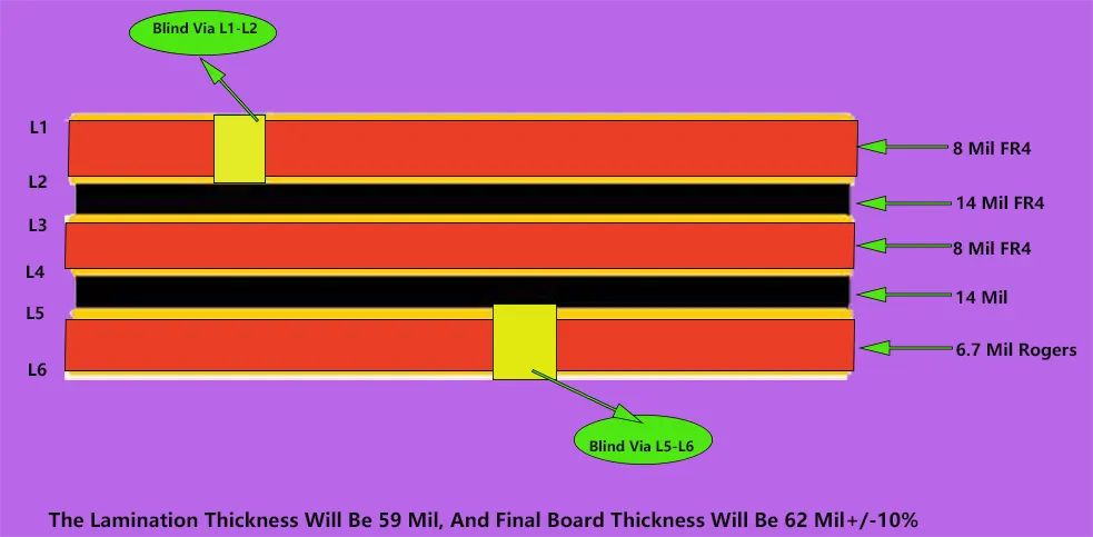
Rogers PCB layers can be mixed together with FR4 layers to provide better performance at a minimum cost vs. all layers are Rogers materials. If this is the case, then the signals must be placed on the Rogers PCB core, not on the prepreg.
A common FR4 6-layer stack-up is illustrated below. The prepreg is located in the outer layer to lower costs since prepreg has cheaper than cores. This is commonly referred to as”foil build”
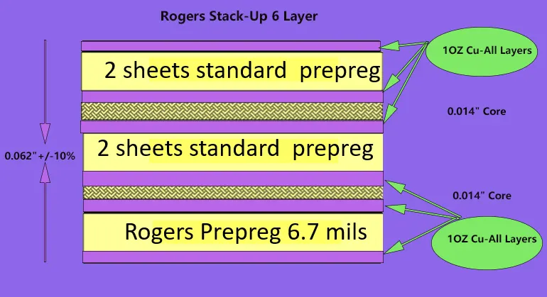
But it is the case that when the Rogers layer is required, the core is placed on the layers that require it, which are typically the outer layers. Check out the example below that has three cores instead of two, like the example above. This type of configuration is often called”Cap Construction “, Cap Construction” board or”core build” “core build”.
 FR4 Mix Rogers PCB Stack Ups
Challenges and Solutions of Rogers PCB Manufacturing and Assembly
Common Manufacturing Challenges
When it comes to manufacturing Rogers PCBs, a few bumps in the road can pop up, often stemming from the unique characteristics of Rogers materials. Here’s a breakdown of some common challenges and how to tackle them like a pro.
Brittleness of Rogers Materials
One of the main challenges is the brittleness of certain Rogers materials. This property can make cutting and shaping during the fabrication process a bit tricky. If not handled with care, these materials can crack or chip, leading to production delays and increased costs.
Solution:Using specialized cutting tools and techniques can help mitigate this issue. For instance, employing laser cutting instead of traditional milling can offer more precision and reduce the risk of damage. Plus, adjusting the parameters of the machinery, like speed and pressure, can go a long way in keeping those materials intact.
Thermal Expansion Mismatches
Another hurdle is the thermal expansion mismatch between Rogers materials and the copper used in PCBs. When heated, these materials can expand at different rates, which might lead to delamination or warping of the board during soldering.
Solution:To tackle this issue, choosing the right material combinations and keeping a close eye on the temperature during soldering is a must. Engineers might also use controlled cooling techniques to ease thermal shock and keep everything under control. This way, you can ensure your assemblies stay solid and reliable!
| Challenge | Description | Solution |
| Brittleness of Materials | Risk of cracking or chipping during fabrication | Use laser cutting; adjust machinery parameters |
| Thermal Expansion Mismatches | Different expansion rates between materials | Control temperature during soldering; use controlled cooling techniques |
Handling Moisture Absorption
Rogers materials can also absorb moisture, which might compromise the board’s performance over time. If moisture seeps into the material, it can lead to issues like signal loss or even complete failure of the PCB.
Solution:Implementing a rigorous drying process before and during the manufacturing stages is essential. Using moisture barriers during storage and transport can also protect these materials from absorbing humidity, ensuring they remain in top-notch condition.
Example: Consider a telecommunications company that faced challenges with signal integrity in their high-frequency devices. By addressing the brittleness of their Rogers materials and employing specialized cutting techniques, they were able to produce more robust PCBs. After fine-tuning their assembly process to mitigate thermal expansion mismatches, they saw a marked improvement in product reliability.
Therefore, navigating the challenges of Rogers PCB manufacturing and assembly requires a mix of ingenuity and technical know-how. By understanding the common pitfalls and implementing tailored solutions, engineers can streamline production processes and deliver high-quality products that meet the demands of today’s technology landscape. So, roll up your sleeves and tackle these challenges head-on—success is just a smart solution away!
FAQ About Rogers PCB
What is a Rogers PCB?
Rogers PCBs are high-performance circuit boards made from specialized materials designed for RF and microwave applications. They excel in maintaining signal integrity at high frequencies.
Why Choose Rogers PCBs Over FR-4?
Rogers PCBs offer superior thermal stability and lower dielectric loss compared to FR-4 materials, making them ideal for high-frequency applications in telecommunications and aerospace.
What are the Common Applications of Rogers PCBs?
Rogers PCBs are widely used in telecommunications, aerospace, military, and high-frequency RF applications, providing reliable performance in demanding environments.
How Can I Select the Right Rogers PCB Manufacturer?
Look for manufacturers with a proven track record in Rogers PCB fabrication, relevant certifications, and strong customer support. Consider their ability to offer custom solutions tailored to your specific needs.
What are the Key Challenges in Designing Rogers PCBs?
Common challenges include material selection, ensuring proper impedance control, and managing thermal performance. Addressing these issues early in the design process can lead to better outcomes.
Wrapping Up
 Rogers PCB
Summary of Rogers PCB Fabrication and Assembly Advantages
Rogers PCBs stand tall in high-frequency applications, offering a range of benefits that give businesses a competitive edge. With cutting-edge materials and innovative fabrication techniques, these boards deliver outstanding performance where it matters most. Their superior thermal stability and dielectric properties ensure reliable signal transmission, making them the go-to choice for industries like telecommunications and aerospace.
At JarnisTech, we’re not just in the PCB game; we’re here to revolutionize it. With over 20 years of experience under our belts, we blend advanced technology with expert engineering to provide you with top-notch Rogers printed circuit boards. Our commitment to quality means you can count on us for timely deliveries at prices that won’t break the bank.
We understand that when it comes to PCBs, you need a partner who’s got your back. That’s why we pride ourselves on being responsive and ready to tackle any challenge you throw our way. Whether you’re looking for custom solutions or standard offerings, we’ve got the goods to meet your needs.
For the inside scoop on our PCB fabrication and assembly services, don’t hesitate to check out our website. If you’ve got questions or need a quote, drop us a line at [email protected] or give us a call at 0086-0755-23034656. Let’s make your next project a resounding success!
Our special materials
PCB Fabrication
Rogers PCB Laminates & Series


