Printed circuit board (PCB) fuses are compact, board-mounted components engineered to provide overcurrent protection. They function as a sacrificial device within an electronic circuit, designed to open and interrupt the flow of current when it exceeds a predetermined level. This action safeguards sensitive electronics from damage caused by short circuits or overload conditions, thereby ensuring the safety and operational integrity of the entire system.
The Fundamental Operating Mechanism
A PCB fuse’s protective function stems from the physical principle of Joule heating. This conversion of electrical energy into thermal energy is how the component averts circuit damage during overcurrent events. Understanding this mechanism provides a clear view of how the fuse delivers reliable circuit protection.
Summary of Operation
●Thermal Melting: Fuses function based on the Joule heating effect (P=I2R). Excessive current causes an internal metallic element to heat and melt.
●Physical Interruption: This melting action creates a permanent physical gap in the circuit, achieving fault isolation.
●Single-Use Device: A standard fuse is a single-use protective device that requires replacement after the fault is resolved.
The Fuse Activation Process
The metallic element within a fuse is precisely calibrated; its resistance and melting point determine its protective behavior in a circuit.
1.Normal Operating State
Under standard conditions, current flows through the fuse element with negligible thermal buildup. The minimal heat generated dissipates without affecting circuit performance, allowing the fuse to act as a simple conductor.
2.Overcurrent Fault Condition
In the event of a fault, such as a short circuit or component failure, the current passing through the fuse surges far beyond its rated capacity.
3.Thermal Interruption Mechanism
●Rapid Heating: The surge in current, governed by the power formula (P=I2R), causes a rapid accumulation of heat within the element.
●Melting and Opening the Circuit: Once the temperature reaches the specific melting point of the element’s alloy, the metal liquefies and vaporizes. This phase change creates a physical gap, opening the circuit.
4.Fault Isolation
The open circuit immediately halts the flow of destructive current, shielding downstream components from damage. A standard fuse provides one-time protection and must be replaced after the root cause of the fault has been identified and rectified.
A Systematic Classification of PCB Fuses
To effectively navigate the vast landscape of available components, a systematic classification is essential. Fuses are categorized based on key performance characteristics and physical attributes that directly influence their application suitability. This structured approach allows engineers to narrow down the options and focus on the types of fuses that align with their specific protection requirements, from high-speed semiconductor safeguarding to managing high-inrush industrial loads.
Key Takeaways:
●Three Core Dimensions: Fuses are primarily classified by their response time (speed), applicable current type (AC/DC), and physical form factor.
●Speed Dictates Application: Fast-acting types protect sensitive semiconductors, while slow-acting types permit harmless inrush currents from loads like motors.
●Form Factor Impacts Manufacturing: Surface-mount (SMD) fuses are suited for automated production and high-density boards, while through-hole types offer greater mechanical strength.
To select the appropriate fuse, it is necessary to understand how they are categorized based on their performance, physical construction, and intended application. These classifications provide a framework for matching a fuse to specific protection needs.
Response Time Characteristics (Fusing Speed)
This classification describes the time it takes for a fuse to open in response to a specific level of overcurrent. The choice is determined by the sensitivity of the components being protected.
●Very Fast-Acting (Ultra-Rapid): These fuses offer the quickest response, designed to protect highly sensitive semiconductor devices like microcontrollers and MOSFETs which can be damaged by even very brief current surges. They have minimal tolerance for normal operational inrush currents.
●Fast-Acting (F-Type): Providing a balance of speed and resilience, this common fuse type is suitable for general-purpose protection of less sensitive components and circuits, such as resistive loads, where it can tolerate minor, harmless power-on transients.
●Slow-Acting (Time-Delay / T-Type): These fuses incorporate a thermal delay mechanism that allows them to withstand predictable, temporary inrush currents from motors, transformers, or large capacitor banks without opening. The fuse will only open if the overload condition persists, preventing nuisance trips in high-draw applications.
Current and Voltage Type Specifications
Fuses are designed differently for alternating current (AC) and direct current (DC) circuits, primarily due to the physics of arc extinction.
●AC Fuses: In AC circuits, the current waveform naturally crosses zero volts multiple times per second. This zero-crossing point helps to extinguish the electrical arc that forms as the fuse element melts, making AC fuses generally more compact for a given voltage rating.
●DC Fuses: DC circuits maintain a constant voltage, meaning an arc, once formed, can sustain itself. DC fuses must therefore be constructed more robustly, often with larger internal gaps or special arc-quenching fillers like sand, to safely interrupt the current and extinguish the persistent arc.
Physical Form Factor and Mounting Technology
The physical package of a fuse dictates how it integrates onto the PCB, affecting board density, manufacturing processes, and serviceability.
●Surface-Mount Device (SMD) Fuses: These are miniature, rectangular components soldered directly onto the PCB surface. Ideal for automated high-volume assembly, SMD fuses are the standard choice for space-constrained electronics like mobile devices and wearables.
●Through-Hole Fuses: Featuring wire leads that pass through holes in the PCB, these fuses are soldered on the opposite side. They offer superior mechanical strength, making them suitable for high-vibration environments or higher-power applications. Some are designed for use with sockets, enabling easier replacement.
Strategic Selection Criteria for Application-Specific Fuses
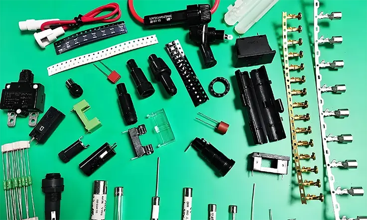
Selecting a suitable fuse for a specific application involves a systematic evaluation of multiple parameters, extending beyond a simple current rating. An appropriate choice balances electrical ratings, the operating environment, and applicable compliance standards.
Selection Fundamentals
●Electrical Ratings: The selection must align with the circuit’s voltage, current, melting integral (I2t), and interrupting capacity.
●Safety Margins: The fuse’s current rating typically includes a margin (e.g., 135% of the normal operating current), and its interrupting capacity must substantially exceed the maximum potential system fault current.
●Environmental Factors: The ambient operating temperature directly affects a fuse’s tripping behavior, requiring its current rating to be derated based on the application’s thermal conditions.
| Parameter | Key Consideration | Example Value / Range |
| Voltage Rating | Must ≥ maximum circuit voltage | 32V, 125V, 250V |
| Current Rating | ~135% of normal operating current | 1.35× normal load current |
| I²t | Matches component’s withstand energy | 0.1–50 A²s |
| Interrupting Capacity | Must > max potential fault current | 35A, 1500A, 10kA (application-dependent) |
| Temp Derating | Reduce current rating at higher ambient temperatures | –25% at +85 °C |
Electrical Ratings and Performance
These parameters define the fuse’s foundational protective capabilities.
●Current Rating: The nominal current a fuse can carry indefinitely without degradation. The rating is typically chosen to be 135-150% of the maximum steady-state operating current to avoid nuisance trips while providing protection.
●Voltage Rating: The maximum system voltage the fuse can safely interrupt. Exceeding this rating may result in a failure to clear a fault due to a sustained arc.
●Interrupting Capacity: Also known as breaking capacity, this indicates the maximum prospective fault current the fuse can handle without rupturing or causing a hazard. It must exceed the system’s worst-case short-circuit current.
●Melting Integral (I2t): This value represents the thermal energy needed to open the fuse. For effective protection, the fuse’s total let-through energy must be lower than the energy withstand capability of the component it protects.
| Parameter | Definition | Typical Values / Notes |
| Current Rating | Continuous current without degradation | 0.1–20 A (PCB fuses) |
| Voltage Rating | Max safe interrupt voltage | 32V DC, 125V AC, 250V AC |
| Interrupting Capacity | Max fault current safely interrupted | 35A–10kA |
| I²t | Thermal energy needed to melt fuse element | Lower values = faster blow |
| Fuse Speed | Response time (Fast / Slow) | Fast-Acting, Time-Delay |
Environmental and Physical Factors
The operating environment and physical layout place additional constraints on fuse selection.
●Ambient Temperature: A fuse’s current-carrying capacity decreases as the ambient temperature rises. Manufacturers provide derating curves to adjust the effective current rating based on the operational thermal environment.
●Physical Dimensions: The fuse’s footprint and height must be compatible with the PCB layout and enclosure constraints.
●Agency Approvals: For commercial products, selecting fuses that meet safety standards from recognized bodies (e.g., UL, IEC) is necessary for compliance and market access. Look for markings corresponding to standards like the UL 248 or IEC 60127 series.
PCB Fuse Selection Checklist
This framework guides the selection process, ensuring all relevant parameters are considered.
Electrical Performance Verification
●Voltage Rating: Is the fuse’s voltage rating equal to or greater than the maximum circuit operating voltage?
●Current Rating: Has the nominal current rating been selected (e.g., ~135% of max operating current) and then derated for the maximum ambient temperature?
●Interrupting Capacity: Is the fuse’s interrupting capacity greater than the maximum potential fault current of the system?
●Energy Coordination (I2t): Is the fuse’s total let-through energy less than the damage threshold of the component it protects?
●Response Time: Has the fuse speed (Fast-Acting vs. Slow-Acting) been chosen to match the circuit’s inrush current characteristics?
●Current Type: Is the fuse correctly rated for the circuit’s current type (AC or DC)?
Physical and Compliance Verification
●Physical Footprint: Does the fuse package (SMD, Through-Hole) and its dimensions fit the allocated space on the PCB layout?
●Certifications: Does the fuse carry the required safety certifications (e.g., UL, VDE, AEC-Q200) for the product’s target market and application?
●Mechanical Robustness: For high-vibration environments, has a mechanically robust fuse type been selected?
●Manufacturer Datasheet: Have all specifications been verified against the official manufacturer’s datasheet?
Verifying these numerous specifications and sourcing authenticated components can present a challenge. Our end-to-end service model, which covers the entire scope from component procurement to final PCB assembly, is structured to streamline this procedure and ensure every part aligns with the design specifications.
Fuse Coordination and Selectivity in Hierarchical Protection Schemes
In systems with multiple layers of circuit protection, devices must be coordinated to ensure only the one nearest a fault opens. This practice, known as selectivity, isolates faults to the smallest possible area, which maximizes system uptime and simplifies diagnostics. Verification involves comparing the Time-Current Curves (TCCs) and energy values (I2t) of the upstream and downstream fuses to ensure a non-overlapping gap exists in their performance.
Coordination and Analysis Methods
Proper coordination prevents localized faults from causing widespread system interruptions.
1.Total vs. Partial Selectivity
Total selectivity ensures the downstream fuse will open before the upstream device under all possible fault conditions. Partial selectivity indicates this coordination is only guaranteed up to a certain level of fault current.
2.Time-Current Curve (TCC) Analysis
This method involves comparing the TCCs of fuses in series. For coordination to be effective, the curve of the downstream (load-side) fuse must not intersect the curve of the upstream (source-side) fuse. A distinct gap must be maintained between the curves.
3.Energy-Based Coordination (I2t)
For very high-current faults that cause fuses to open in under 10 milliseconds, TCC analysis may not provide sufficient accuracy. In these scenarios, coordination relies on comparing energy values. The total let-through energy (I2t) of the downstream fuse must be less than the melting energy (I2t) of the upstream fuse.
The Impact of Manufacturing Processes on Fuse Performance
A fuse’s performance, as specified on its datasheet, is contingent on proper handling during assembly. The thermal and mechanical stresses of manufacturing, if not carefully controlled, can degrade a fuse’s internal element and compromise its protective function. Adherence to manufacturer-recommended process parameters is necessary to ensure the component’s final performance aligns with its design specifications.
Manufacturing and Assembly Risks
●Thermal Stress Risk: An improper soldering temperature profile, especially excessive peak heat or duration, can pre-damage the internal fuse element, leading to premature failure during its service life.
●Physical and Chemical Risk: Physical forces during PCB depaneling or the use of aggressive cleaning solvents can also compromise the fuse’s structural integrity.
Thermal Stresses from Soldering
The soldering process is the most significant thermal event a fuse experiences during assembly.
Reflow Soldering Profile
For SMD fuses, the reflow oven’s temperature profile—including preheat time, peak temperature, and time above liquidus—must be kept within the limits specified by the fuse manufacturer. Excessive heat can partially damage the fuse element, lowering its current-carrying capacity and making it prone to nuisance trips later in its life.
Wave and Manual Soldering
For through-hole fuses, excessive heat application time or temperature from a wave or a soldering iron can migrate up the leads and damage the internal element. Proper technique and temperature control prevent this type of damage.
Mechanical and Chemical Stresses
Physical handling and post-solder processing can also introduce latent damage.
PCB Depaneling
Mechanical stress during depaneling (separating individual boards from a larger panel) can transmit forces to components. If a fuse is placed too close to a breakaway tab or V-groove, the resulting board flexion can crack the fuse’s ceramic body or its solder joints.
Washing and Cleaning
The chemical agents and high pressures used in some board cleaning processes can be detrimental. Aggressive solvents may compromise the fuse’s markings or body integrity. The solution is to use fuses specified as resistant to cleaning agents or to adopt a no-clean flux process where appropriate.
Fuses in High-Reliability (Hi-Rel) Applications
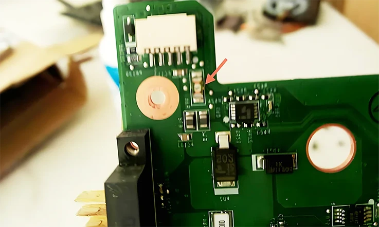
Fuses intended for sectors like automotive, medical, and aerospace must meet standards far exceeding those for conventional electronics. In these applications, where component failure can have severe outcomes, fuses must provide accurate protection while also showing exceptional robustness against harsh environments. This requires adherence to stringent, domain-specific quality and safety certifications.
Core Requirements for Hi-Rel Applications
●Industry Standards: Components must pass specific industry certifications (e.g., AEC-Q200 for automotive, IEC 60601-1 for medical).
●Environmental Robustness: Fuses must be built to withstand extreme temperatures, severe vibration, and shock.
●Design Considerations: Certain applications, such as dual-fusing in medical devices, reflect a heightened focus on safety and fault tolerance.
Automotive Systems
The automotive environment is characterized by wide temperature ranges, constant vibration, and high electrical transients.
●AEC-Q200 Qualification Any fuse intended for automotive use must be qualified to the AEC-Q200 standard. This involves a series of rigorous stress tests, including thermal cycling, vibration, and humidity testing, to ensure the component’s durability and long-term reliability.
●Functional Safety (ISO 26262) While a system-level standard, ISO 26262 requires a systematic approach to hazard analysis. Proper circuit protection with qualified fuses is a foundational part of meeting the required Automotive Safety Integrity Levels (ASIL).
Medical Devices
In medical equipment, design is governed by the need for patient and operator safety, as outlined in standards like IEC 60601-1.
●Dual Fusing The IEC 60601-1 standard often specifies dual fuses on both the line and neutral connections of the main power input. This design ensures the device is completely isolated from the mains power in a fault event, a concept known as “two means of protection.”
●Low Leakage Current All components, including fuses and their holders, must be selected to contribute minimally to the system’s overall leakage current to safeguard patients.
Aerospace and Defense
Aerospace applications introduce challenges of vibration, g-forces, and operation in a vacuum.
●High Vibration and Shock Resistance Fuses must be mechanically robust, often with specialized mounting or ruggedized packages to prevent failure under extreme mechanical stress.
●Low Outgassing In the vacuum of space, materials can release trapped gasses (“outgassing”), which can condense on sensitive optical or electronic surfaces. Components, including fuses, are selected for their low-outgassing properties, often conforming to NASA or ESA specifications.
Advanced Fuse Technologies and Architectures
The demand for smaller and more robust electronics has led to innovations in circuit protection. Advanced fuse architectures now offer capabilities like self-resetting and extreme miniaturization, enabling protection in applications where conventional fuses are impractical.
Overview of Modern Fuse Technologies
●Reset-ability: PPTC resettable fuses provide a solution for applications where faults are transient and manual replacement is difficult, automatically restoring function after a cool-down period.
●Miniaturization: Thin-film fuse technology utilizes semiconductor manufacturing processes to create highly precise protective devices in extremely small packages, supporting modern high-density electronics.
Resettable Fuses (PPTC Devices)
Polymeric Positive Temperature Coefficient (PPTC) devices offer a self-recovering alternative to traditional one-time fuses.
●Operating Principle A PPTC consists of a polymer matrix filled with conductive carbon particles. During an overcurrent event, Joule heating causes the polymer to expand, separating the carbon particles and transitioning the device to a high-resistance state. When the fault is cleared and the device cools, it returns to its low-resistance state.
●Application Profile They are well-suited for applications where transient overloads are common and manual replacement is impractical, such as in USB ports or motor circuits.
Thin-Film and High-Density Fuses
The drive for miniaturization has led to the development of fuses manufactured with semiconductor-like processes.
●Construction and Benefits Produced using photolithography on a ceramic substrate, these fuses offer highly precise and repeatable characteristics in extremely small packages (e.g., 0402, 0201). Their stability and compact size make them a frequent choice for high-density circuits in mobile phones, wearables, and other portable devices.
Component Sourcing and Supply Chain Integrity
A meticulously designed circuit protection scheme is rendered useless if the physical component installed on the PCB is counterfeit or substandard. The integrity of the supply chain is not an administrative detail but a fundamental requirement for product reliability and safety.
Core Tenets
●Risk of Counterfeits: Using a non-genuine fuse creates a false sense of security and can lead to protection failure, resulting in equipment damage or fire hazards.
●The Solution: The only dependable method to ensure component authenticity is to procure parts from the Original Component Manufacturer (OCM) or their officially authorized distributors.
Ensuring Component Authenticity
The effectiveness of a circuit protection design is ultimately determined by the authenticity and quality of the components used.
1.Dangers of Unverified Components
●A counterfeit or unverified fuse may have an incorrect current rating, a different response time, or a dangerously low interrupting capacity. It fails to provide effective protection and poses a direct threat to the product and its user.
2.The Function of Authorized Distribution
●Verified Chain of Custody: Authorized distributors receive their inventory directly from the OCM, which eliminates the risk of counterfeits and ensures components are handled and stored according to industry standards.
●Access to Technical Resources: These suppliers provide direct access to manufacturer datasheets, application notes, and expert technical support—a valuable resource during the design and debugging phases.
Turnkey Manufacturing: Integrating Protection from Design to Assembly
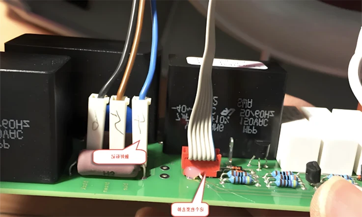
Effective circuit protection is not achieved by selecting a single component, but through a holistic process where design intent is accurately translated into a physical product. A turnkey manufacturing partner provides this integration, cohesively managing every stage from design review and component sourcing to fabrication and assembly.
Advantages of a Turnkey Service
●Holistic Viewpoint: A turnkey service treats circuit protection as an integrated process spanning design, procurement, and manufacturing, not as an isolated component choice.
●Proactive Prevention: Design for Manufacturability (DFM) analysis identifies and corrects fuse integration and layout issues before production begins, mitigating future risks.
●Integrated Value: By combining component sourcing, high-specification PCB fabrication, and precision assembly, a turnkey service ensures the protection scheme is implemented accurately and reliably.
The Pillars of a Turnkey Service
1. Proactive Design for Manufacturability (DFM): This early-stage review bridges the gap between design and physical production. DFM analysis checks the PCB layout for issues related to fuse integration—such as incorrect land patterns, insufficient clearances for safety standards, or inadequate trace widths for fault currents—allowing for corrections before costly fabrication begins.
2. Controlled Fabrication and Assembly: The quality of the physical board and the assembly process determines final reliability. A capable turnkey provider has expertise in a wide range of PCB materials, from FR-4 to polyimide for rigid-flex boards, and maintains precise control over fabrication and assembly. This ensures the physical board can support the thermal and mechanical demands of the chosen protection scheme.
3.Integrated and Vetted Supply Chain: The turnkey model inherently includes component sourcing. A provider with a vetted, global supply chain procures authentic, high-quality fuses as part of the service, streamlining logistics and guaranteeing component integrity.
By partnering with a turnkey provider, you transform circuit protection from a series of isolated tasks into a single, managed process, resulting in a more robust and reliable end product.
Case Study: Designing Overcurrent Protection for a 12V Industrial IoT Gateway
Theory provides a foundation, but its value is revealed in practice. To synthesize the concepts from this guide, this section presents a step-by-step design case study. We will walk through a realistic engineering scenario to show how system requirements are translated into a specific, justified, and robust fuse selection. This example synthesizes concepts of response time, temperature derating, and industry standards into a single, cohesive design choice.
1. System Requirements Analysis
Device: An Industrial IoT Gateway for remote monitoring.
Input Voltage: 12V DC nominal.
Current Profile:
●Maximum steady-state operating current: 450mA.
●Inrush current on startup (from cellular module): 2.0A for 500µs.
Environment:
●Operating temperature: -20°C to +70°C.
●Application: Industrial, requires high reliability and tolerance to moderate vibration.
| Parameter | Value | Notes |
| Input Voltage | 12V DC | Nominal |
| Steady-State Current | 450mA | Continuous load |
| Inrush Current | 2.0A | Lasts 500µs at startup |
| Operating Temperature | -20°C to +70°C | Industrial grade |
| Environment | Moderate vibration | Requires high mechanical robustness |
2.Initial Current Rating Calculation
Using the 135% rule as a starting point:
●Minimum Fuse Rating = 450mA×1.35=607.5mA
●A standard fuse value above this, such as 750mA or 1A, would be the initial consideration.
3.Inrush Current Tolerance Analysis (I2t)
The startup inrush pulse must be analyzed to prevent nuisance tripping.
●Inrush Energy (I2t) = (2.0A)2×500µs=4.0×0.0005=0.002A2s
●We consult datasheets for 750mA fuses. A typical fast-acting fuse might have a melting I2t of 0.0015 A²s, which is less than the inrush energy, so it would trip. A slow-acting fuse of the same rating might have a melting I2t of 0.01 A²s, which is well above the inrush energy.
●Decision: A Slow-Acting fuse is required.
4.Environmental Derating
The fuse must operate reliably at the maximum temperature of +70°C.
●We consult the manufacturer’s derating curve for the chosen slow-acting fuse family. At +70°C, the curve indicates the fuse must be derated by 20% (i.e., it will only carry 80% of its nominal rating).
●Required Nominal Rating at 25°C = (Minimum Fuse Rating) / (Derating Factor)
●Required Nominal Rating at 25°C = 607.5mA/0.80=759.4mA
●This calculation confirms that a 750mA fuse is borderline, while a 1A fuse provides a healthy margin.
| Parameter | Value |
| Minimum Fuse Rating | 607.5mA |
| Derating Factor @ +70°C | 0.80 |
| Required Nominal @ 25°C | 759.4mA |
| Final Decision | 1A for margin |
5. Final Component Selection & Justification
Final Choice: A 1A, 32VDC, Slow-Acting, AEC-Q200 qualified, 1206 SMD fuse.
Justification:
●1A: Provides sufficient margin above the derated operating current.
●32VDC: Safely exceeds the 12V system voltage.
●Slow-Acting: Tolerates the known inrush current pulse.
●AEC-Q200 Qualified: Ensures robustness for the industrial vibration and temperature environment.
●1206 SMD: A common, robust package suitable for automated assembly.
6.PCB Layout Considerations
●The layout will feature wide copper traces connecting to the fuse pads to aid in heat dissipation. The fuse will be placed near the 12V input connector to protect the entire board, and kept separate from sensitive analog sensor inputs to prevent noise coupling.
This case study demonstrates a methodical workflow for component selection. A systematic, data-driven approach is fundamental to our turnkey design and assembly process, ensuring that every protective device is not just specified, but purposefully chosen to deliver on the reliability and safety requirements of the final product.
What Defines a Premier One-Stop PCB Service?
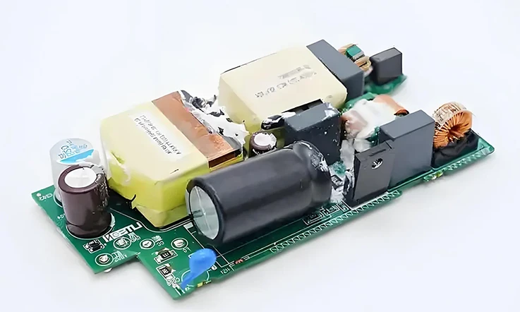
The preceding guide illustrates the immense detail involved in just one aspect of board design—circuit protection. This complexity multiplies across every component and process. Therefore, selecting a manufacturing and assembly provider is a decision that dictates a project’s ultimate success. A premier one-stop service provider moves beyond being a simple vendor to become an extension of the engineering team, distinguished by comprehensive, integrated capabilities.
End-to-End Component Sourcing and Management
A top-tier service begins with a robust and transparent supply chain. This involves more than just purchasing parts; it is a sophisticated logistics and quality assurance function. Attributes include:
●A global network of authorized distributors to guarantee component authenticity and prevent counterfeit risks.
●Proficiency in managing long-lead-time components, mitigating supply chain disruptions, and handling specialized parts for high-frequency or high-power applications.
This integrated sourcing capability removes a significant burden from the client, reduces project delays, and ensures every component, from the simplest resistor to the most complex processor, is genuine and reliable.
Advanced PCB Fabrication Capabilities
The foundation of any electronic assembly is the bare printed circuit board. A leading provider offers a wide spectrum of fabrication technologies to meet the demands of modern electronics. This includes not only standard multi-layer rigid boards but also advanced constructions such as:
●Rigid-flex PCBs.
●High-Density Interconnect (HDI) with microvias.
●Boards utilizing specialized materials for RF and microwave applications.
Expertise in controlled impedance, heavy copper, and fine-line manufacturing, all backed by in-process quality control like Automated Optical Inspection (AOI) and bare-board electrical testing, is the hallmark of a superior fabrication facility.
Precision PCB Assembly (PCBA) Expertise
The assembly stage is where the design truly comes to life. A reliable PCBA service is characterized by state-of-the-art, automated assembly lines capable of handling a vast range of components with high precision. This includes the placement of:
●Fine-pitch BGAs.
●Ultra-small passives (such as 0201 or 01005 packages).
The capabilities extend to both Surface-Mount Technology (SMT) and Through-Hole Technology (THT), including specialized processes like conformal coating for environmental protection. The process is validated by rigorous inspection and testing protocols to guarantee the final product performs exactly as designed. These protocols include:
●3D Automated Optical Inspection (3D AOI).
●X-ray inspection for non-visible solder joints (e.g., BGAs).
●In-Circuit Testing (ICT).
●Comprehensive Functional Testing (FCT).
Collaborative Partnership and Technical Support
A leading provider acts as a partner, not just a manufacturer. This means providing seamless communication and deep technical support. Hallmarks of this partnership include a dedicated project manager for a clear, single point of contact; transparent progress reporting that keeps the client fully informed; and accessible engineering support throughout the entire process. This collaborative approach, from DFM feedback to production problem-solving, is what truly makes a provider an extension of the client’s engineering team.
Frequently Asked Questions (FAQ)
This section provides rapid, clear answers to common questions regarding the application and behavior of PCB fuses, serving as a quick reference for engineers and technicians.
Q1: Is it acceptable to replace a blown fuse with one that has a higher ampere rating?
A: Absolutely not. This is a critical safety risk. The fuse’s rating is precisely chosen to protect the circuit’s components. Using a higher-rated fuse defeats this protection and can lead to catastrophic board damage or fire. Always use an exact replacement.
Q2: Why would a fuse open if there isn’t a direct short circuit?
A: A fuse opens in response to any overcurrent. This can be caused by a sustained overload from a failing component, an incorrect fuse choice (e.g., using a fast-acting fuse in a high-inrush circuit), or long-term fatigue from repeated current pulses.
Q3: What is the difference between a fuse’s current rating and its interrupting capacity?
A: The Current Rating is the maximum current the fuse can handle continuously. The Interrupting Capacity is the maximum fault current it can safely stop without rupturing.
Q4: How does a high-altitude or high-humidity environment affect a fuse?
A: At high altitudes, thinner air reduces cooling, which may cause a fuse to open at a slightly lower current. In high humidity, moisture can degrade the PCB’s insulation, increasing the risk of electrical arcing across the fuse after it opens.
Q5: Is it safe to use an AC-rated fuse in a DC circuit?
A: No, this is unsafe. An AC fuse relies on the current’s zero-crossing to extinguish an arc. In a DC circuit, an arc can be sustained indefinitely, causing the fuse to fail and creating a fire hazard. Always use a fuse specifically rated for the DC application.
References and Further Reading
For more detailed technical information and to ensure compliance with the latest standards, consulting primary source documents is recommended.
●IEC 60127 Series: The international standard for miniature fuses.
●UL/CSA 248 Series: The primary North American standards for low-voltage fuses.
●AEC-Q200: The global standard for stress test qualification of passive electronic components for automotive applications.
●ISO 26262: The international standard for functional safety of electrical and electronic systems in road vehicles.
●IPC-2152: The industry standard for determining current-carrying capacity in printed circuit board design.
Application notes and technical handbooks on circuit protection provided by reputable fuse manufacturers.


