
The successful deployment of high-performance electronics on the Shengyi SAR20 aluminum substrate is born from an intimate relationship between its material science and the precision of the fabrication process. This guide provides a manufacturing-centric examination of this synergy, detailing the advanced fabrication, quality control, and engineering philosophy required to translate thermal potential into reliable, finished printed circuit boards. It furnishes a complete technical foundation covering material composition, design guidelines, and the procurement of high-reliability circuits built with the SAR20 material system.
Shengyi SAR20 Material System: A Technical Breakdown
The performance characteristics of a Shengyi SAR20 thermal substrate are a direct outcome of its three core components: the aluminum base, the ceramic-filled dielectric, and the copper foil. The meticulous handling of each element during fabrication dictates the final board’s thermal capabilities and long-term reliability.
The Aluminum Base: More Than a Structural Support
The aluminum core provides both structural stability and a thermal pathway. Its processing directly influences board planarity, mechanical integrity, and final assembly yields.
●Dimensional Stability Control: The inherent rigidity of a 1.0mm to 2.0mm aluminum base provides a formidable defense against the warpage that afflicts large FR-4 panels during thermal excursions. Specialized clamping systems and pre-bake thermal stabilization cycles are employed before solder mask application to hold panel flatness to a tolerance often below 0.75%.
●Precision Machining: The machinability of the selected 5052 or 6061 aluminum alloy permits the use of advanced tooling, including diamond-coated (PCD) routing bits and multi-stage peck-drilling cycles. The result is clean, burr-free edges and exact hole locations, a prerequisite for seamless automated assembly and robust mechanical mounting.
●Surface Preparation: Before lamination, the aluminum undergoes a proprietary chemical and mechanical pre-treatment. This step is engineered to heighten the bond strength with the dielectric layer, preventing delamination during strenuous thermal shock tests (-40°C to +125°C) and securing dependable operation in harsh automotive or industrial environments.
Aluminum Base Properties:
| Property | Typical Values |
| Base Thickness | 1.0mm – 2.0mm |
| Flatness Tolerance | < 0.75% |
| Alloy Types | 5052 / 6061 |
| Pre-treatment Type | Chemical + Mechanical |
| Thermal Shock Range | -40°C to +125°C |
The Dielectric Layer: The Core of Thermal Transfer and Isolation
The 75µm to 150µm ceramic-filled epoxy dielectric governs both thermal performance and electrical safety. Its processing requires meticulous and unwavering control.
●Void-Free Lamination: A carefully managed lamination sequence, utilizing controlled temperature ramps and high-pressure vacuum cycles, promotes complete resin flow. This creates a void-free insulating layer—a non-negotiable condition for passing high-potential (Hi-Pot) tests at voltages scaling up to 3kV, verified through cross-sectional analysis.
●Controlled Thickness for Thermal Impedance: Dielectric thickness is a primary factor in thermal resistance. Sophisticated process controls maintain this thickness within a +/-10% tolerance, which guarantees predictable heat transfer from components to the aluminum base across an entire production batch.
●High Peel Strength with Heavy Copper: SAR20 is frequently specified with 2oz (70µm) or 3oz (105µm) copper. The dielectric system is chemically formulated to sustain a high peel strength (>10 lb/in) after thermal stress, effectively preventing trace lifting during assembly or throughout the product’s operational lifespan.
Dielectric Layer Specifications:
| Parameter | Typical Values |
| Dielectric Thickness | 75µm – 150µm |
| Thermal Resistance Control | +/-10% |
| Hi-Pot Test Voltage | Up to 3kV |
| Peel Strength with 3oz Copper | >10 lb/in |
| Lamination Tolerance | Tightly controlled via vacuum lamination |
The Copper Foil: Path for Power and Signal
The formation and finishing of the copper layer are adapted for the demands of high-power applications, housing the electrical circuit itself.
●Fine-Line Etching on Heavy Copper: Achieving fine-line trace widths on 3oz copper requires a multi-stage etching process with advanced etchant chemistry. This approach minimizes undercut and produces straight, clean trace sidewalls, enabling the design of high-current-density layouts without degrading electrical performance.
●Surface Finish Compatibility: Application processes for finishes such as ENIG, Lead-Free HASL, or OSP are specifically calibrated for SAR20 substrates. For example, temperature profiles for HASL are engineered with a slower ramp rate. This adjustment accounts for the significant thermal mass of the aluminum, preventing thermomechanical stress that could otherwise compromise the board’s structural integrity.
Advanced Fabrication for Complex Geometries
Executing complex mechanical features on a SAR20 substrate provides functional advantages that enable higher power density, smaller form factors, and more durable integration into final assemblies. These capabilities merge PCB fabrication with precision metalworking techniques.
Multi-Level Machining for Component Integration
High-precision CNC milling creates three-dimensional topography within the aluminum base, allowing for sophisticated component mounting and thermal management strategies.
●Stepped Pockets and Cavities: Controlled-depth milling creates recessed areas in the aluminum base. This allows power components to be mounted lower, reducing the overall Z-axis height of the assembly and creating a more direct, lower-resistance thermal path from the component case to the aluminum core.
●Embedded Component Structures: For applications requiring extreme density, cavities can be machined to allow for the embedding of passive components directly into the substrate. This frees up surface area on the top circuit layer for other functions.
●Precision Depth Control: These milling operations are held to depth tolerances often within +/-50µm. This level of precision ensures proper component seating and a predictable bond line thickness for thermal interface materials, directly influencing the effectiveness of thermal transfer.
Integrated Fastening and Mounting Solutions
Mechanical interfaces machined directly onto the board simplify final assembly and enhance the product’s structural integrity.
●Countersinking and Counterboring: These features allow flat-head or socket-head screws to sit flush with or below the board surface. The process is executed with specialized tooling that prevents stress concentration or damage to adjacent circuit features.
●Tapped (Threaded) Holes: For applications requiring frequent assembly cycles or high clamping force, holes in the aluminum base can be directly tapped to accept machine screws. This approach eliminates the need for separate nuts and washers, simplifying the bill of materials and streamlining the assembly workflow. Thread quality is verified to secure long-term mechanical stability under vibration.
Board Edge and Interconnection Technologies
Features crafted on the board’s perimeter can provide enhanced electrical properties and unique assembly methods.
●Edge Plating for Shielding: This process involves routing the board profile, followed by a chemical sequence to prepare the exposed aluminum and dielectric for plating. A continuous copper-plated shield is then formed along the board edges, an effective technique for EMI containment in demanding automotive and RF power applications.
●Castellated Holes for SMT Mounting: Plated through-holes located on the board edge are precisely bisected during routing to create solderable half-holes. This allows the entire SAR20 PCB to be mounted as a surface-mount component onto a larger parent board, enabling highly modular power system designs.
[To evaluate the feasibility of complex geometries in your design, submit your files for a complimentary DFM analysis.]
Advanced Via Technology for Thermal Management
On a Shengyi SAR20 PCB, thermal vias function as direct conduits for thermal energy, channeling it from a surface component to the aluminum heat sink. The design and fabrication of effective thermal vias in a metal-backed substrate demand a detailed understanding of materials and process controls.
The Physics and Design of an Effective Thermal Via
The effectiveness of a thermal via is measured by its thermal resistance (Rth), a value governed by its physical properties set during design and fabrication.
●Via Diameter and Plating Thickness: Thermal resistance is inversely proportional to the via’s cross-sectional area and the thickness of its copper plating. A larger diameter and a thicker copper barrel (targeting >25µm) create a wider, more conductive path. Design practices often favor an array of smaller vias (e.g., 0.3mm to 0.6mm diameter) over a single large one to distribute heat more evenly and mitigate mechanical stress.
●Via Filling for Enhanced Conduction: An open via can trap air and contaminants, impeding heat transfer. Filling the via barrel addresses this.
1.Non-Conductive Epoxy Fill: A thermally stable epoxy fills the via, which is then planarized and can be plated over (Via-in-Pad). The fill provides structural support, prevents solder wicking during assembly, and allows components to be placed directly over the via array.
2.Conductive Epoxy Fill: A silver-filled epoxy can be used to augment the via’s thermal conductivity. This method, however, adds cost and process complexity, requiring careful management of the CTE mismatch between the fill and the copper barrel.
3.Solid Copper Plugging: The option offering the lowest thermal resistance involves electroplating the via completely solid with copper. This creates a nearly homogenous copper pillar and is reserved for the most demanding thermal applications.
●Via-in-Pad Plated Over (VIPPO): To maximize heat transfer, thermal vias are placed directly within a component’s solder pad. The VIPPO process fills and then plates a flat copper cap over the via, creating a smooth, solderable surface. This design provides the most direct heat path by eliminating the thermal detour that occurs when vias are placed adjacent to the pad.
Fabrication Challenges and Solutions for Thermal Vias
Creating durable thermal vias in a composite material like SAR20 requires specific solutions for known manufacturing challenges.
●Clean Hole Drilling: Drilling through copper, ceramic-filled epoxy, and into an aluminum backup plate is a multi-stage process. Specialized drill bits and controlled peck-drilling cycles are used to prevent resin smear on the hole’s copper sidewalls, which would otherwise compromise plating adhesion.
●Void-Free Barrel Plating: Following drilling, the desmear and hole-wall conditioning steps are meticulously controlled. Any residue can cause voids or weak spots in the electroplated copper. A uniform, continuous copper barrel is a prerequisite for achieving both the specified thermal performance and long-term durability.
●Managing CTE Mismatch: During thermal cycling, the copper barrel (CTE ≈ 17 ppm/°C) and the surrounding dielectric/aluminum (CTE ≈ 12-24 ppm/°C) expand and contract at different rates. This inherent stress is managed by employing high-ductility copper plating chemistry and designing via arrays that effectively distribute stress, preventing localized fatigue failures.
| Material | CTE (ppm/°C) | Relevance |
| Copper | ~17 | High ductility helps absorb expansion stress |
| SAR20 Dielectric | ~12–16 | Compatible with copper and aluminum expansion |
| Aluminum Base | ~22–24 | CTE delta managed by copper ductility & design |
Quality Validation of Thermal Via Structures
The integrity of thermal via structures is verified through defined quality control methods.
●Automated Optical Inspection (AOI): Post-drilling, high-resolution AOI systems verify hole position accuracy and check for any debris that could affect subsequent plating.
●Cross-Sectional Analysis: Sample coupons from panels are periodically extracted, mounted, and polished. Microscopic examination of the cross-section allows for direct measurement of copper plating thickness, evaluation of plating uniformity, and assessment of via fill integrity.
| Parameter Analyzed | Acceptance Criteria | Methodology |
| Copper Thickness | ≥ 25 µm in via barrel | Optical microscopy at 200–400× magnification |
| Fill Coverage | ≥ 95% of via volume | Visual and X-ray confirmation |
| Plating Uniformity | ±10% across panel | Statistical sampling and mapping |
●Thermal Shock Testing: As a lot acceptance test, finished boards are subjected to extreme temperature cycles (e.g., -40°C to +125°C). Subsequent cross-sectional analysis of these stressed boards confirms the via structures can withstand the thermomechanical forces expected in their end-use environment.
High-Voltage Application Integrity: Creepage, Clearance, and Insulation
Shengyi SAR20 is frequently specified for power conversion and automotive systems operating at high voltages. Such applications place stringent demands on electrical safety and long-term insulation reliability. The substrate’s aluminum base acts as a large ground potential plane, which requires exacting control over the dielectric layer’s integrity and the physical separation of conductors. The processes used to meet and verify these high-voltage requirements are detailed below.
Creepage and Clearance in a Metal-Core Context
While sometimes used interchangeably, creepage and clearance are distinct concepts with specific manufacturing implications.
1.Clearance (Air Gap):
This is the shortest distance through the air between two conductive elements. While primarily controlled by the layout design, the fabrication process must ensure etching and plating operations do not reduce this intended air gap below the specified minimum.
2.Creepage (Surface Path):
This is the shortest path along an insulator’s surface between two conductors. The high Comparative Tracking Index (CTI) of SAR20 (typically ≥600V) provides a strong defense against the formation of conductive carbon tracks on the surface when moisture and electrical stress are present.
3.Manufacturing for Isolation:
To achieve reliable isolation, fabrication is geared towards preserving specified distances. This includes using high-resolution imaging to define copper features with precision and employing routing paths that create clean board edges without conductive burrs that could compromise creepage paths. Isolation slots milled between high-voltage sections are a common feature requiring precise CNC control.
The Dielectric Layer as the Primary Insulation Barrier
The Shengyi SAR20 dielectric layer is the primary barrier against high-voltage breakdown to the grounded aluminum core. Its integrity is a direct function of the lamination and material handling processes.
1.Guaranteed Minimum Dielectric Thickness:
While a datasheet specifies a nominal thickness (e.g., 100µm), the manufacturing process is controlled to guarantee a minimum thickness after lamination. This practice prevents localized thin spots that could become points of high electrical stress and potential failure.
2.Void-Free Lamination:
The absence of voids or trapped air pockets within the dielectric is a prerequisite for high-voltage applications. Voids cause a significant reduction in dielectric strength and are a primary source of failure during Hi-Pot testing or in the field. A controlled vacuum lamination process is employed to eliminate this risk.
3.Material Purity:
The raw SAR20 material and the fabrication environment are maintained at a high level of cleanliness. Any embedded foreign object or metallic debris within the dielectric can severely compromise its insulation capability by acting as a potential breakdown point.
Verification and Compliance with Safety Standards
High-voltage designs must function correctly and demonstrate compliance with international safety standards such as IEC 62368-1. This compliance is confirmed through methodical testing.
100% High-Potential (Hi-Pot) Testing:
This non-destructive test is applied to every high-voltage board. A DC voltage (e.g., 500V to 3000V) is applied between the shorted copper layers and the aluminum base for a set duration. The test measures leakage current, and a board passes if the current remains below a specified threshold (e.g., <10mA) with no dielectric breakdown. This test provides definitive confirmation of the insulation integrity for each unit.
Solder Mask as Supplemental Insulation:
The solder mask provides an additional layer of dielectric protection. The application process ensures complete coverage over all high-voltage traces, without pinholes or skips. The solder mask’s own dielectric strength contributes to the overall integrity of the insulation system.
Documentation for Certification:
For products requiring agency certification (e.g., UL, VDE), a full documentation package is available. It includes material datasheets, cross-section reports, and records of Hi-Pot testing. This documentation supports and streamlines the agency certification process for the end product.
Achieving Controlled Impedance on Shengyi SAR20 Hybrid Designs
Modern electronic design sees the convergence of high-power circuitry and high-speed digital logic onto single substrates. While Shengyi SAR20 is engineered for thermal management, its application in hybrid constructions with FR-4 signal layers, or as a double-sided board, introduces the necessity for controlled impedance. The ability to execute a thermal board with precise impedance profiles is a function of mastering the interplay between thermal and electrical parameters.
The Necessity for Controlled Impedance in Power Systems
Impedance control is fundamental to preserving signal integrity. For high-frequency signals, a PCB trace behaves as a transmission line. Should the impedance of this line fluctuate or fail to match the driver and receiver, the resulting signal reflections will degrade performance and risk component damage.
●High-Speed Gate Drivers:
The fast switching speeds of Silicon Carbide (SiC) and Gallium Nitride (GaN) transistors are governed by gate driver signals with rapid rise times. These signals are highly susceptible to distortion from impedance mismatches. A controlled impedance path delivers a clean, sharp pulse to the gate, enabling efficient power conversion and reducing switching losses.
●Communication Buses:
Automotive and industrial systems frequently route communication protocols such as CAN or Ethernet on the same board as power electronics. These protocols operate under specified impedance standards (e.g., 120 Ω for CAN, 100 Ω for Ethernet) to ensure error-free data transmission, even within electrically noisy environments.
●Clock and Data Lines:
The reliable operation of on-board microcontrollers and FPGAs depends on controlled impedance for clock lines and other high-speed data interfaces.
Governing Physical Factors for Impedance
Attaining a target impedance (e.g., 50 Ω single-ended, 100 Ω differential) is a direct result of precise control over trace geometry and the properties of the dielectric material. These variables are interdependent.
●Dielectric Constant (Dk) and Material Stability:
The dielectric constant of the Shengyi prepreg is a primary input for impedance calculations. An accurate outcome relies on material with a well-documented Dk value. A thorough understanding of how this value may shift during lamination, combined with the stability of the SAR20 resin system from one batch to the next, is a precondition for predictable impedance outcomes.
●Dielectric Height (H):
This dimension, the insulation thickness between a signal trace and its reference plane, is meticulously managed during the lamination cycle. Precision pressing and carefully selected prepreg sheets are employed to achieve a final cured thickness within a tight tolerance (e.g., ±10%).
●Trace Geometry (W & T):
The copper trace’s cross-sectional geometry also governs the final impedance. The trace thickness (T) is determined by the starting copper foil weight and any subsequent plating. The trace width (W), defined by photolithography and etching, must be exact. Advanced etching systems compensate for process variables, ensuring the final trace width matches the layout dimensions with high fidelity, often within ±10-15µm.
Process Modeling and Verification with TDR Measurement
Delivering specified impedance is a two-stage sequence: predictive modeling followed by empirical verification. This approach mitigates risk by confirming design theory with physical measurement.
●Pre-Build Modeling:
The process begins during the Design for Manufacturability (DFM) review. Using 2D field solver software, the required trace dimensions and spacing are calculated based on the specified impedance, the designated layer stack-up, and the known SAR20 material properties. This generates a highly accurate theoretical model before the physical build commences.
●Empirical Verification with TDR:
To provide objective proof of compliance, test coupons are embedded on the master panel alongside the deliverable boards. These coupons feature traces built with the calculated geometries. After the build cycle, a Time-Domain Reflectometer (TDR) is used to test these coupons. The TDR sends a fast-rise-time pulse down the trace and measures any reflections, generating a precise impedance profile along the line. The resulting data serves as a certificate of quality, confirming the build process yields boards that meet the specified impedance tolerance (e.g., 50 Ω ±10%).
[Planning a hybrid design with controlled impedance? Consult Our Engineering Specialists on Your Stack-Up]
The Thermomechanical Lifecycle: Designing for Long-Term Reliability
The true measure of a high-performance printed circuit board is not its function on day one, but its unwavering operation over thousands of hours, across countless thermal cycles, and in the face of harsh environmental conditions. Understanding and designing for the thermomechanical lifecycle of a Shengyi SAR20 board separates a merely functional product from one that is truly robust.
Managing the Inherent Forces of CTE Mismatch
The interplay of materials within a SAR20 substrate presents a complex physics challenge. The aluminum base, the ceramic-epoxy dielectric, and the copper circuitry all expand and contract at different rates when heated and cooled. This difference in the Coefficient of Thermal Expansion (CTE) is an inescapable reality of the assembly.
●Understanding the Stress: This differential expansion creates immense internal stress within the board structure. The stress is primarily concentrated at material interfaces, such as the dielectric-to-aluminum bond, and within the vertical structures of plated through-holes.
●Mitigation Through Material Science: The SAR20 resin system is engineered as a “toughened” epoxy, providing a degree of flexibility to absorb these stresses without fracturing. A superior chemical bond, achieved through advanced aluminum surface preparation, serves as the first line of defense against delamination.
●Mitigation Through Design: Thoughtful layout practices also contribute to stress reduction. Distributing heat-generating components to avoid intense, localized thermal gradients helps minimize stress concentration in specific areas of the board.
Countering Fatigue in Vias and Interconnects
Plated vias, particularly the thermal vias integral to IMS performance, are highly susceptible to fatigue failure under thermal cycling. Repeated expansion and contraction along the Z-axis can, over time, lead to circuit failure.
●The Failure Mechanism: The primary failure mode is barrel cracking, where a fatigue crack forms in the plated copper wall of the via, creating an open circuit. A related failure is pad lifting or cratering, where stress pulls the annular ring away from the substrate.
●The Plating Solution: A primary defense against via fatigue is the application of high-ductility electroplated copper. Unlike standard copper, this specially formulated plating is more malleable, allowing it to stretch and deform slightly with each thermal cycle without cracking. Achieving this property requires exacting control over the plating bath chemistry, including organic additives and current density.
●Verification: The durability of these structures is not assumed; it is proven. Aggressive thermal shock testing followed by micro-sectional analysis is performed to confirm the absence of stress fractures or signs of fatigue.
Preserving Lamination Integrity Over Time
The bond between the layers of a SAR20 board must remain intact for the entire operational life of the product, often a decade or more in challenging environments.
●Defending Against Moisture: Moisture ingress is a primary adversary to lamination integrity. The low moisture absorption rate of the SAR20 dielectric, typically below 0.3%, is a beneficial material property. This characteristic, a result of a void-free lamination process, prevents moisture from compromising the bond between layers, especially under high-humidity conditions.
●Glass Transition Temperature (Tg): The Tg of the dielectric is the temperature at which the epoxy resin transitions from a rigid, glassy state to a more pliable state. The Tg of SAR20’s resin is engineered to be well above the maximum operating temperatures of its target applications, ensuring the board remains mechanically stable throughout its functional range.
Panelization and Depaneling Strategies for Aluminum Substrates
Panelization, the method of arranging multiple smaller PCBs into a single larger manufacturing panel, enables efficient, high-volume assembly. For aluminum-backed substrates like Shengyi SAR20, the panelization and subsequent depaneling strategy is far more consequential than for standard FR-4. The mechanical properties of the aluminum core demand specialized techniques to manage stress, maintain dimensional accuracy, and ensure a clean final board edge.
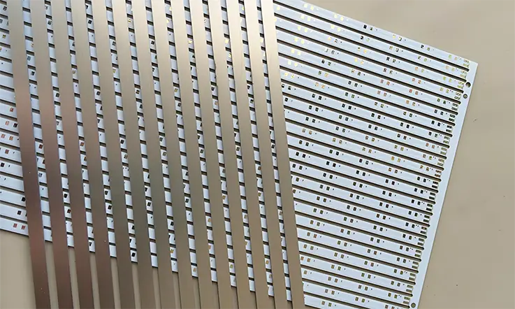
V-Scoring (V-Grooving) for SAR20 Panels
V-scoring is a swift and economical method for depaneling boards with straight-line perimeters. Its application to aluminum, however, requires exceptional precision.
●The Process: A cutting tool with angled blades (typically 30, 45, or 60 degrees) scores a V-shaped groove along the top and bottom surfaces of the panel. The remaining material between the grooves is called the “web.” The boards are later separated by cleanly breaking them along this weakened line.
●Aluminum-Specific Control:
1.Web Thickness: For SAR20, the residual web thickness is carefully controlled. If it is too thick, excessive force is needed to break the panel, which can flex the board and stress surface-mounted components. If it is too thin, the panel may be too flimsy to handle during assembly. A typical web for a 1.6mm SAR20 board is controlled to a range of 0.4mm to 0.5mm.
2.Blade Condition and Alignment: The cutting blades must be exceptionally sharp and perfectly aligned. Dull blades will tear the aluminum instead of shearing it, creating significant burrs and a rough, unacceptable edge finish. Polycrystalline Diamond (PCD) blades are often employed for their extended lifespan and cutting precision on abrasive materials.
●Best Use Cases: V-scoring is a preferred method for large arrays of rectangular or square boards, such as linear LED modules or power supply units, where assembly speed and low cost are priorities.
Tab-Routing for Complex Board Shapes
When PCBs have curved edges or intricate outlines, tab-routing is the designated method. It offers great design flexibility but requires a different set of process controls.
●The Process: A CNC router uses a high-speed spinning cutter bit to machine the full outline of each board, leaving behind small tabs of material to hold the board securely in the panel. After assembly, these tabs are broken or cut to free the board.
●Aluminum-Specific Control:
1.Router Bit Selection: Standard FR-4 router bits wear out almost instantly against the abrasive aluminum and ceramic-filled dielectric. Specialized diamond-coated or solid carbide “chipbreaker” style bits are used. These are designed to manage heat and abrasion while producing a smooth edge finish.
2.Tab Placement and Style: The number, location, and style of the tabs are determined by experience. Tabs are placed in areas of low mechanical stress, away from sensitive components. Perforated tabs (often called “mouse bites”) can make board separation easier but may require a post-depaneling finishing step. Solid tabs are stronger but must be professionally cut.
●DFM Considerations for Panel Stability: Panel-level design must account for stresses introduced during assembly. For example, large, asymmetrical copper pours can cause the entire panel to warp during solder reflow. Copper thieving patterns are often added in the panel’s scrap areas to balance these stresses and ensure the panel remains flat. The panel border must also include accurate tooling holes and fiducial marks for machine alignment.
Quality Assurance and Reliability Verification
For electronics operating in demanding environments, performance is not assumed; it is verified. The assembly of Shengyi SAR20 solutions relies on systemic process control and rigorous verification, ensuring every board delivered is ready for the rigors of its intended application.
Electrical Integrity and Insulation Validation
The electrical integrity of a SAR20 PCB is defined and confirmed by several principal parameters engineered into each unit.
●Dielectric Withstanding Voltage (Hi-Pot): A 100% Hi-Pot test is performed on high-voltage designs. This confirms the insulating layer between the copper and the aluminum substrate can withstand specified voltage surges (e.g., >=3kV), mitigating leakage risk during real-world overload conditions.
●Comparative Tracking Index (CTI): The high CTI value of the SAR20 material (typically >=600V) provides a robust defense against surface tracking. This failure mode can be caused by contaminants or condensation, and a high CTI is a strong indicator of long-term reliability in industrial controls.
●Insulation Resistance: This test validates the long-term ability of the resin system to isolate DC voltages without significant current leakage, even after prolonged exposure to heat and humidity (e.g., >=10^8 Ohm after 96h @ 85°C/85%RH).
Thermomechanical and Environmental Stress Testing
Boards built with SAR20 materials undergo rigorous testing designed to simulate years of harsh field operation, providing confidence in their long-term durability.
●Thermal Shock and Cycling Resistance: The laminated structure must withstand rapid temperature cycling, often from -40°C to +125°C for hundreds of cycles without failure. This is achieved through a resin system with balanced elasticity and a low CTE mismatch between the copper and aluminum, a direct result of a controlled lamination process.
●Moisture Absorption and Delamination Resistance: Low moisture absorption (typically <0.3%) is achieved through a low-porosity dielectric layup and a high-adhesion solder mask application. This prevents moisture ingress that could degrade electrical performance. The boards must also exhibit minimal delamination or blistering after exposure to multiple solder reflow cycles.
●Micro-sectioning and Material Analysis: Beyond electrical tests, physical analysis provides direct, physical evidence of build quality. Cross-sections are regularly prepared from completed panels to visually inspect and measure designated structures like copper plating thickness in holes, the integrity of the dielectric layers, and the quality of the lamination bond. This provides indisputable evidence of process control.
Failure Analysis and Root Cause Determination on IMS
True expertise is revealed not only in building flawless products but also in the profound understanding of how and why they might fail. A deep, forensic approach to failure analysis provides actionable data for process improvement and gives designers confidence that potential risks are understood and mitigated. For Insulated Metal Substrates (IMS) like SAR20, failure analysis is a specialized discipline.
Common Failure Modes in Thermal PCBs
While robustly designed and built, IMS boards can exhibit specific failure modes under extreme stress or due to subtle interactions between the design and build process.
●Dielectric Breakdown: A catastrophic failure where the insulation layer between the copper circuit and the aluminum base is punctured, resulting in a short circuit. This can be caused by transient voltage spikes exceeding the material’s dielectric strength or by microscopic defects within the dielectric.
●Interconnect Failure (Via Cracking): Thermal cycling can induce stress at the interface between the plated copper via barrel and the surrounding laminate due to CTE mismatch. Over time, this can lead to fatigue cracks, creating an open circuit, especially in thermal vias under large components.
●Delamination: The separation of layers, either between the copper foil and the dielectric or the dielectric and the aluminum base. This can be triggered by excessive thermal stress (e.g., improper assembly profiles), moisture ingress, or contamination at a bonding interface.
Forensic Analysis Techniques
Identifying the true root cause of a failure requires a methodical investigation using sophisticated analytical tools.
●High-Resolution Optical and SEM Inspection: The initial investigation often starts with non-destructive, high-magnification optical inspection. For deeper analysis, a Scanning Electron Microscope (SEM) is used. SEM provides extremely high-magnification images of a failure site (e.g., a crack surface), revealing details about the failure mechanism, such as fatigue versus brittle fracture.
●Cross-Sectional Analysis: This technique provides a direct view of the board’s internal structure. The board is carefully cut through the area of interest, mounted in an epoxy puck, and polished to a perfectly smooth surface. This allows for microscopic examination, making it possible to measure dielectric thickness, identify voids or contaminants, assess plating quality in a via, and trace a crack’s origin.
●Energy-Dispersive X-ray Spectroscopy (EDX/EDS): When used with an SEM, EDX analysis identifies the elemental composition of materials at a failure site. This method is effective for identifying foreign contaminants that may have initiated a dielectric breakdown or a bonding failure.
●Thermal Imaging (Infrared Thermography): For failures that occur under power, thermal imaging can be used to pinpoint hotspots on a board. This can reveal issues like a poorly performing thermal via array or unexpected current crowding that could be the root cause of overheating and subsequent failure.
Design & Procurement Framework for SAR20 PCBs
Procuring specialty PCBs made with Shengyi SAR20 involves a balance of technical requirements, quality expectations, and commercial considerations. A transparent and capable supplier provides a clear framework that connects design choices to final cost, quality level, and delivery schedule. This allows for informed decision-making without sacrificing performance.
Design for Manufacturability (DFM) Review
Before any material is cut, a thorough DFM review specific to the nuances of aluminum substrates is conducted. The objective of this review is to align the design with established build processes, ensuring high-yield and reliable outcomes.
●Thermal Design Analysis: The review checks for common thermal design issues, such as insufficient copper for heat spreading under power components, a lack of thermal vias, or the presence of thermal bottlenecks caused by isolated copper pours.
●Mechanical Feature Verification: The DFM process verifies that all mechanical features—like cutout radii, countersink depths, and the spacing between features—are compatible with high-yield CNC machining processes.
●High-Voltage Clearance Check: For applications requiring high-voltage isolation, the layout is checked against established build rules for creepage and clearance distances, ensuring the design can be reliably built to meet safety standards.
Factors Influencing Unit Price
The cost of a SAR20 PCB is driven by more than just raw material. Build complexity and specified assurance levels are determining factors in the final price.
●Material Selection: The thickness of the aluminum base (1.0mm vs. 2.0mm) and the copper weight (1oz vs. 3oz) are direct cost drivers. Thicker materials offer better thermal mass and current capacity but increase material cost and processing time.
●Build Complexity: Features like multiple cavity milling, countersunk holes, edge plating, or tapped holes require additional CNC machine time and specialized tooling, which adds to the unit price. A detailed DFM review can often identify ways to achieve the design intent more cost-effectively.
●Quality Assurance Level: While standard electrical testing is included, specifying requirements like 100% Hi-Pot testing at a specific voltage, thermal shock testing for lot validation, or the generation of detailed Certificate of Conformance (CoC) reports will influence the final price. These measures, however, reduce the risk of costly field failures.
●Panel Utilization: The efficiency of the board layout on a standard assembly panel (e.g., 18″ x 24″) directly impacts cost. Optimized panelization schemes can substantially reduce material waste and, therefore, the per-unit cost.
Comparative Benchmarking: SAR20 vs. Alternative Thermal Laminates
Selecting the optimal thermal substrate requires a nuanced analysis of performance, processability, and total cost of ownership. Shengyi SAR20 occupies a strategic position in the market, offering a distinct balance of these factors. A direct comparison with other well-known materials clarifies its ideal application space.
Shengyi SAR20 vs. Bergquist Thermal Clad (Henkel)
Bergquist materials represent a long-established standard in the insulated metal substrate (IMS) market. This comparison highlights parallels in performance alongside distinctions in material science and processability.
Thermal Performance and Cost Structure:
Shengyi SAR20 is engineered to offer thermal conductivity values (e.g., 2.0 W/m·K) directly comparable to widely used Bergquist HT and MP series materials. With a highly optimized supply chain and large-scale vertical integration, SAR20 often presents a more advantageous cost structure, enabling high-level thermal performance without an equivalent budget impact.
| Property | Shengyi SAR20 | Bergquist HT-04503 | Bergquist MP-06503 |
| Thermal Conductivity (W/m·K) | 2.0 ± 0.2 | 2.2 ± 0.2 | 1.5 – 2.0 |
| Dielectric Thickness (µm) | 75 / 100 / 150 | 75 / 100 / 150 | 75 / 125 |
| Breakdown Voltage (kV) | ≥ 3.0 | ~3.0 | ~2.5 |
| Total Cost Index (Relative) | 1.00 | 1.25 | 1.30 |
Dielectric Uniformity and Processability:
The SAR20 dielectric exhibits notable batch-to-batch uniformity. This translates to more predictable final dielectric thickness after lamination and more stable dielectric constant (Dk) values, a benefit for designs with tight thermal or electrical tolerances. This material uniformity also results in more predictable tool wear during machining, improving yields.
Shengyi SAR20 vs. Rogers 92ML Series
Rogers Corporation materials are specified for their high-frequency electrical performance. The 92ML series targets a specialized segment where RF properties govern the design.
Application Intent:
This is the clearest distinction. Rogers 92ML is specified when low dielectric loss (Df) and a stable Dk over a wide frequency range are the primary design drivers, as in RF power amplifiers. Shengyi SAR20, conversely, is a thermomechanical workhorse. Its tough, epoxy-based system is optimized for raw heat dissipation and mechanical endurance, making it well-suited for automotive motor drives, industrial power modules, and high-power LED applications.
| Attribute | Shengyi SAR20 | Rogers 92ML |
| Target Application | Power conversion, LED, auto | RF/microwave power amplifiers |
| Electrical Performance Focus | Moderate | Very High (RF-optimized) |
| Thermal Performance | High (2.0 W/m·K) | Moderate (1.5–1.9 W/m·K) |
| Frequency Range Suitability | < 1 GHz | > 1 GHz |
Mechanical Robustness and Cost Profile:
The SAR20 system is highly durable, with high peel strength for heavy copper, making it suitable for environments with high vibration and thermal shock. For applications that do not require the specialized (and more costly) RF properties of the 92ML series, SAR20 delivers the necessary thermal management and durability with a more advantageous cost-performance ratio.
Shengyi SAR20 vs. Ceramic Substrates (AlN, Al2O3)
Ceramic substrates like Aluminum Nitride (AlN) or Alumina (Al2O3) offer the highest levels of thermal conductivity but operate in an entirely different build process and cost paradigm.
Thermal Conductivity vs. Practicality:
In pure thermal conductivity, AlN can exceed 170 W/m·K. However, this extreme performance is coupled with brittleness, high material cost, and severe size limitations. Ceramics require specialized, lower-volume processes like laser cutting and thick-film metallization.
| Property | Shengyi SAR20 | Al₂O₃ Ceramic | AlN Ceramic |
| Thermal Conductivity (W/m·K) | 2.0 ± 0.2 | ~24 | 150–180 |
| Dielectric Strength (kV/mm) | ~20 | >15 | >18 |
| Mechanical Fragility | Low | High | Very High |
| Typical Substrate Thickness (mm) | 0.8 – 1.6 | 0.25 – 0.635 | 0.25 – 0.635 |
Scalability and System Cost:
SAR20 is mechanically robust and leverages scalable circuit board build processes. It can be efficiently produced in large panels, drilled, routed, and V-scored. This makes it highly scalable for high-volume assembly. The total system cost for a ceramic solution is magnified by the non-standard, often manual, assembly processes they require. SAR20 provides the robust, scalable, and cost-effective thermal management solution that the vast majority of high-power electronic applications demand.
FAQs for Shengyi SAR20 PCB Fabrication
Q: What are the main challenges when etching heavy copper (e.g., >=3oz) on SAR20?
A: The primary challenge is controlling etch undercut. To maintain trace width accuracy, a multi-stage etching process with specialized etchants is used to produce straight sidewalls.
Q: Are there specific V-cut parameters for depaneling SAR20 arrays?
A: Yes. A wider V-cut angle (30-45 degrees) and a precisely controlled residual web thickness are used. This combination ensures a clean break while preventing board stress and aluminum burrs.
Q: How are through-holes plated in a hybrid SAR20/FR-4 stack-up?
A: It requires a multi-step hole preparation. The process includes a desmear for the FR-4 layers and a separate conditioning for the SAR20 layers to ensure reliable plating adhesion to both material types.
Q: What type of tooling is used for routing SAR20 to extend tool life?
A: Diamond-coated (PCD) routers and specially-coated carbide drills are standard. This tooling is necessary to resist the abrasive dielectric and manage the heat generated from machining aluminum.
Q: Does an unprocessed SAR20 laminate have specific storage requirements?
A: Yes. Laminates require a climate-controlled environment (20-25C, <50% RH). This prevents moisture absorption, which can cause delamination and other defects during high-temperature fabrication processes.
Application Case Studies: SAR20 in Demanding Environments
Lists of material properties and process capabilities are useful, but the true measure of a substrate and its assembly is demonstrated through successful, real-world applications. These case studies illustrate how the combination of Shengyi SAR20’s characteristics and advanced build processes solve tangible engineering problems.
Case Study 1: Automotive 48V DC-DC Converter
●The Challenge: An automotive Tier 1 supplier was developing a compact 2kW DC-DC converter for a 48V mild-hybrid system. Housed in a sealed enclosure with no active airflow, the unit presented a severe thermal challenge. Their initial prototype, built on a standard IMS material, failed validation as the main power MOSFETs reached temperatures of 115°C, exceeding the design limit and threatening long-term vehicle reliability.
●The Engineering Solution: A thermal simulation confirmed the hotspots and identified the substrate’s thermal resistance as the governing bottleneck. A new build using Shengyi SAR20 was specified, featuring a 1.5mm thick aluminum base, 2oz heavy copper, and a thin 100µm dielectric to minimize thermal impedance. To address the hotspots, a dense array of thermal vias using the Via-in-Pad Plated Over (VIPPO) process was designed directly under the power MOSFETs, creating a highly efficient, direct thermal path from the component’s thermal pad to the aluminum core.
●The Result: The new SAR20-based prototypes delivered a substantial improvement. Under full-load testing, the maximum temperature on the same MOSFETs was reduced by 24°C, stabilizing at a safe 91°C. This thermal margin allowed the engineering group to not only pass all validation tests but also to uprate the converter’s continuous power handling capacity by 10% without altering the product’s form factor. The project successfully moved to high-volume assembly, meeting the end-user’s stringent automotive reliability targets.
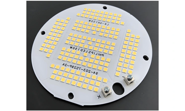
Case Study 2: High-Intensity COB LED Stadium Luminaire
●The Challenge: A manufacturer of professional lighting was designing a 500W LED luminaire for sports stadiums, centered on a single, high-density Chip-on-Board (COB) LED array. The extreme power density was causing significant “thermal droop”—where light output decreases as junction temperature rises—and unacceptable color shift across the playing field.
●The Engineering Solution: Analysis revealed the challenge was not just vertical heat transfer but also rapid lateral heat spreading away from the small COB footprint. A robust solution was chosen: a 3.0mm thick aluminum base for maximum heat spreading, coupled with a Shengyi SAR20 dielectric of only 75µm thickness for the lowest possible thermal resistance. The copper layer under the COB was connected to the aluminum base via an array of over 300 copper-plugged thermal vias. This process created solid copper pillars, offering highly efficient vertical heat transfer. Furthermore, the external surface of the aluminum base was machined to a flatness tolerance of <0.05mm to ensure a near-perfect interface with the luminaire’s large external heat sink.
●The Result: The process-led design was highly effective. The final luminaire’s COB junction temperature was maintained a full 20°C below its maximum rating. This completely eliminated thermal droop, resulting in a 15% higher sustained lumen output. The stable temperature also ensured uniform color rendering, meeting all international broadcasting requirements. The enhanced durability allowed the company to market the product with a 10-year warranty, securing a substantial contract for several new stadium constructions.
A Framework for Excellence in High-Performance PCB Assembly
Executing a successful project with advanced substrates like Shengyi SAR20 extends beyond datasheets and price quotations. It requires an operational framework grounded in technical depth, systemic control, and process optimization. This framework for excellence is built upon several interconnected principles that ensure performance, reliability, and value.
Systemic Quality Assurance
For high-performance electronics, quality is not a final inspection step but a systemic discipline woven into every stage of the build process. It is a demonstrable commitment to process control and verification.
●Systematic Verification: This includes practices such as 100% Dielectric Withstanding Voltage (Hi-Pot) testing for high-voltage designs, regular cross-sectional analysis to verify via plating and layer registration, and full traceability from raw material to finished board.
●Adherence to Stringent Standards: Building in compliance with IPC 6012 Class 2 or the more demanding Class 3 standards provides objective proof of reliability and durability.
●Tangible Outcomes: The result of this systemic approach is a substantial reduction in field failures and an extended operational lifespan for the end product.
Total Cost Optimization through Process Efficiency
An advantageous price point is determined by the lowest total cost of ownership, not just the initial unit cost. Competitive pricing is a natural outcome of maximized efficiency, not compromised standards.
●Waste Reduction: Leveraging advanced DFM analysis and optimized panelization schemes maximizes material utilization and minimizes scrap.
●High First-Pass Yields: A culture of rigorous process control results in exceptionally high first-pass yields, eliminating the hidden costs associated with rework, delays, and variable quality.
●Value Engineering: This involves expert consultation on material selection and design alternatives that can reduce cost without compromising the required thermal or electrical performance.
Schedule Integrity and Predictability
Meeting delivery commitments for complex thermal PCBs requires a highly optimized and transparent workflow.
●Specialized Operations: The use of dedicated assembly lines for aluminum-based substrates eliminates the setup times, cross-contamination risks, and process variations found in general-purpose facilities.
●Robust Supply Chain Management: Maintaining strong relationships with material suppliers like Shengyi ensures a stable inventory of common SAR20 configurations, insulating projects from global supply chain volatility.
●Transparent Workflow: A modern project management system provides real-time visibility into an order’s status, from CAM engineering to final inspection and shipping.
Front-Loaded Engineering and Risk Mitigation
A proactive, engineering-focused approach at the start of a project is a powerful method for mitigating risk and ensuring a smooth path to high-volume assembly.
●Early-Stage Analysis: Engaging in complimentary DFM, DFT (Design for Test), and thermal analysis during the design cycle helps to identify and resolve potential issues before they become costly problems.
●Deep Technical Guidance: Providing direct access to process engineers offers a direct path to resolving complex challenges like hybrid stack-up design, high-voltage isolation strategies, or post-assembly troubleshooting.
●End-to-End Process Accountability: A successful project requires complete ownership of the entire build process, standing behind the quality and performance of the delivered product.
Required Advanced Build Capabilities
Ultimately, this framework is enabled by a suite of advanced, verifiable build capabilities. These are the tools and processes required to execute complex, high-reliability designs.
●Precision 3D Machining: Controlled-depth milling for component cavities and stepped features.
●Advanced Via Technologies: Copper-plugged thermal vias and Via-in-Pad Plated Over (VIPPO) for maximum thermal performance.
●Complex Lamination: Expertise in bonding dissimilar materials for hybrid SAR20/FR-4 multilayer builds.
●High-Frequency Expertise: Proven ability to deliver tightly controlled impedance (+/-10% or better) with full TDR verification reporting.
●Intricate Mechanical Features: High-yield execution of edge plating, castellated holes, and countersunk/tapped holes with clean, burr-free finishes.
[Ready to translate thermal potential into a reliable PCB? Upload Your Gerber Files for a Comprehensive Quote]


