
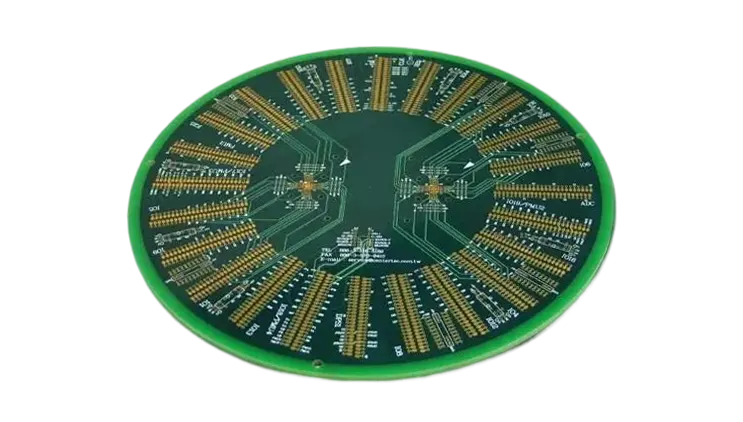
Printed Circuit Board (PCB) coils represent a remarkable fusion of precision engineering and advanced materials science. These components are crafted directly onto circuit boards, providing compact and efficient inductive solutions for modern electronics. As industries continue to demand higher performance from smaller devices, PCB coils have become integral in applications ranging from consumer gadgets to aerospace systems.
This series delves into the nuances of PCB coil technology, covering their design, manufacturing, and practical applications. Whether you’re exploring their role in suppressing electromagnetic interference, their use in high-frequency power systems, or their integration into medical diagnostics, this comprehensive exploration offers a clear roadmap. Along the way, we highlight cutting-edge techniques, from optimizing thermal management in high-power designs to leveraging simulation tools for precision manufacturing.
Introduction: The Future of PCB Coils
In the world of power electronics, PCB Coils have emerged as an integral component, revolutionizing the way we design and manufacture electronic devices. As we continue to push the boundaries of performance, power efficiency, and miniaturization, PCB Coils are steadily taking over traditional inductor designs, especially in high-frequency and high-current applications. But what makes these coils so special, and why is their significance growing? Let’s break down the essentials.
●What Makes PCB Coils Critical in Modern Electronics?
PCB coils are increasingly being adopted in diverse applications such as renewable energy systems, automotive electronics, and IoT devices. Their efficiency and compact design allow us to pack more power into smaller spaces without compromising performance. When we look at a PCB coil, we will see a versatile component that can be tailored to fit any design—whether it’s for EMI shielding, power conversion, or energy storage. This adaptability, combined with high power density, is why PCB coils are becoming so crucial.
●Key Limitations of Traditional Inductor Designs
Traditional inductors, while useful, have their limitations—namely, their size and inefficiency in high-frequency applications. As devices get smaller and more powerful, the need for more compact, energy-efficient inductive components becomes clear. PCB coils offer a solution by integrating the coil directly into the PCB design, minimizing space while improving overall performance.
●Why Rethink PCB Coils?
Today’s power electronics industry is witnessing rapid advancements in technology. From electric vehicles to the booming IoT industry, devices are requiring higher power loads and quicker data processing speeds. PCB coils allow designers to adapt to these changes, ensuring that the devices of tomorrow are efficient, small, and capable of handling complex tasks without overheating or suffering from interference.
The Fundamentals of PCB Coils
PCB coils represent an essential advancement in modern electronics. Unlike traditional inductors, PCB coils are integrated directly into the printed circuit board, making them compact, efficient, and cost-effective for high-performance applications. In this section, we’ll break down what PCB coils are, how they function, and their key applications, showcasing why they are becoming the go-to choice for many industries.
What Are PCB Coils and How Do They Work?
PCB coils are essentially inductive components that are integrated into a PCB rather than being separate components like traditional inductors. These coils use a conductive trace etched onto the PCB to form a coil, allowing them to generate magnetic fields and store energy. When current flows through the trace, the PCB coil operates just like a traditional inductor, storing energy in the magnetic field and resisting changes in current. This makes them a vital component in various power and signal processing circuits.
1.How PCB Coils Function-
When a current passes through a PCB coil, it generates a magnetic field that interacts with the flow of electrons, effectively regulating the current while filtering or converting power. PCB coils can perform functions like power filtration, energy conversion, and current management.
●Energy storage: They store electrical energy and release it when needed.
●Filtering: They filter signals, eliminating high-frequency noise in power supplies and communication systems.
●Inductance: They provide the required inductance for various filtering, smoothing, and power conversion tasks.
2.Example in Power Conversion-
In a switching power supply, a PCB coil helps stabilize the output by filtering fluctuations and reducing ripple. This ensures a consistent current flow, which keeps sensitive electronic devices functioning as intended. It’s like having a steady hand on the wheel, maintaining the smooth delivery of power for optimal performance.
3.Why Choose PCB Coils-
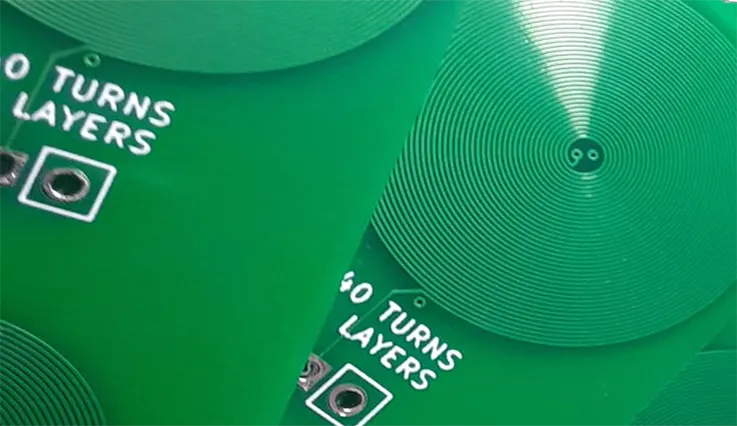
PCB coils are designed with a compact structure that embeds the coil directly into the circuit board, enabling efficient use of limited space. This streamlined configuration is particularly suited for applications where size constraints are significant, such as wearable electronics and automotive systems. By optimizing the layout to maximize functionality without increasing the overall footprint, these coils offer a practical solution that meets the growing demand for miniaturized components.
PCB Coil vs. Traditional Inductors: A Comparison
The primary difference between PCB coils and traditional inductors lies in their form factor, efficiency, and integration into the circuit. While traditional inductors are standalone components that require additional space, PCB coils are directly integrated into the PCB layout itself, offering space-saving and efficiency benefits. Let’s take a closer look at how these two compare.
| Feature | Traditional Inductors | PCB Coils |
| Size | Larger; occupies more space on the PCB | Compact; integrated into the PCB design |
| Efficiency | Less efficient at high frequencies | More efficient at high frequencies |
| Customization | Limited flexibility | Highly customizable based on design needs |
| Cost | More expensive due to separate component sourcing | More cost-effective due to integrated design |
| Thermal Management | May require heat dissipation solutions | Lower thermal rise, better for compact designs |
| Current Handling Capacity | Limited by core material and size | Can handle higher currents with multi-layer PCB designs |
| Inductance | Fixed inductance, varies by component | Customizable inductance values, ranging from uH to mH |
The Key Differences:
●Efficiency at High Frequencies: PCB coils are much better at handling high-frequency signals, making them ideal for RF applications and high-speed circuits. Traditional inductors, especially larger ones, are less effective at higher frequencies due to their bulk and inefficiency.
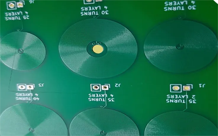
●Customization: Traditional inductors are fairly standardized, whereas PCB coils can be tailored in terms of inductance, current capacity, and even thermal management by adjusting the trace width, number of turns, and layer count on the PCB.
●Cost and Integration: Since PCB coils are integrated into the PCB itself, the overall system cost can be reduced. Traditional inductors require additional sourcing and assembly, which increases the overall cost.
Common Applications of PCB Coils in Electronics
PCB coils are finding increasing applications across industries due to their flexibility, compact design, and enhanced performance in high-frequency environments. Below are some of the most common uses of PCB coils in today’s electronics.
1.EMI Filtering-
Electromagnetic interference (EMI) presents a persistent challenge in power electronics and communication systems. PCB coils serve as an effective shield against EMI by selectively blocking unwanted high-frequency signals while allowing desired ones to pass through unimpeded. This ability to filter and manage signals ensures that devices like power supplies, smartphones, and computers maintain their performance without disruption from external electronic noise. Such precision in signal handling keeps these systems humming along seamlessly, providing reliability even in environments prone to interference.
| Application | Benefit | Example |
| EMI Filtering | Blocks high-frequency noise, reducing signal distortion | Power supplies, motor controllers |
| Signal Processing | Filters specific frequencies for clean output | Communication systems, radio receivers |
| Energy Storage | Stores and releases energy efficiently | Power converters, battery chargers |
2.Power Conversion-
PCB coils are commonly employed in power converters like DC-DC and AC-DC converters, thanks to their ability to efficiently store and release energy. By smoothly managing this energy flow, these coils help maintain steady voltage levels, minimize power losses, and boost the overall efficiency of power supplies. This characteristic makes PCB coils a go-to solution for systems that require precise power regulation and effective energy management, ensuring devices remain reliable and energy-efficient even under fluctuating load conditions. Simply put, they keep everything running without a hitch, making them a dependable component in modern power conversion systems.
| Device | Function | Benefit |
| DC-DC Converters | Converts DC voltage levels | Ensures efficient energy transfer |
| AC-DC Converters | Converts AC to DC voltage | Provides stable, regulated output |
| Battery Charging Systems | Manages current flow for efficient charging | Minimizes charging time, improves battery life |
3.Signal Processing-
In signal processing applications, PCB coils can be used to filter or smooth out signals in circuits such as amplifiers, sensors, and radios. They help to eliminate unwanted frequencies, ensuring the desired signal is clean and strong for further processing.
| Application | Benefit | Example |
| Amplifiers | Filters unwanted noise, ensuring clear output | Audio systems, radio equipment |
| Sensors | Provides stable readings by filtering out noise | Industrial sensors, environmental monitoring devices |
Key Design Principles for High-Performance PCB Coils
Designing PCB coils that can perform under high power conditions requires a deep understanding of several key parameters, from inductance and current handling to trace geometry and material selection. With the demand for smaller, more powerful electronics, PCB coils have become an indispensable component, offering an ideal solution for high-frequency, high-power applications. But to create high-performance PCB coils, the following design principles must be carefully considered.
Core Factors in Designing PCB Coils for High Power
When designing PCB coils for high-power applications, it’s all about making sure your design handles the demands without overheating, suffering from signal loss, or failing prematurely under load. These core factors—inductance, current handling capacity, and trace geometry—must be balanced to achieve optimal performance.
1.Inductance-
Inductance is a crucial parameter in coil design, determining the ability of the coil to store energy. The required inductance depends on the application—whether for power conversion, EMI filtering, or energy storage. PCB coils need to be tuned to provide the precise inductance needed to handle the current and voltage requirements of the device. Over- or under-sizing the inductance can lead to inefficiencies or failure in performance.
| Design Parameter | Effect | Impact on High Power Applications |
| Inductance | Determines energy storage and response to changing currents | Ensures smooth power delivery and filtering |
| Current Handling Capacity | The maximum current the coil can handle before overheating | Critical for high-power electronics like power converters and motor controllers |
| Trace Geometry | Influences resistance and efficiency of the coil | Affects the overall power efficiency and thermal performance |
2.Current Handling Capacity-
PCB coils used in high-power applications must handle higher currents without excessive heat generation. The current handling capacity of a PCB coil is largely influenced by the size and layout of the traces. Properly designed trace width and layer stacking help mitigate resistance and reduce heat buildup.
| Current Level | Trace Width | Heat Generation |
| Low Current | Narrow traces | Minimal heating |
| High Current | Wider traces, multi-layer design | Higher heat dissipation needs |
3.Trace Geometry-
The geometry of the traces impacts the resistance and thermal behavior of the PCB coil. A coil designed with optimized trace geometry ensures the minimum possible resistance, which translates into lower energy losses and better performance under high currents. The layout must also allow for optimal heat dissipation to avoid thermal overload.
Optimization Techniques for PCB Coil Layouts
Designing PCB coils involves much more than simply winding traces into a spiral. It requires a thoughtful layout that maximizes heat dissipation, ensures signal clarity, and ensures the coil can handle various electrical loads efficiently. Careful attention to techniques like layer stacking, trace spacing, and managing heat flow is necessary for developing reliable and high-performing PCB coils. These strategies help optimize the design for specific needs, ensuring the coil performs consistently and meets the demands of your electronic systems, even under changing conditions. By focusing on these design elements, you can maximize efficiency and durability, keeping your systems functioning at their best.
1.Layer Stacking-
For high-power applications, multiple layers of traces are used to enhance the current handling capacity and reduce the overall thermal resistance of the PCB coil. Layer stacking allows us to design compact coils while distributing the heat more efficiently. The use of multi-layer PCBs ensures the coil maintains its electrical performance without excessive heat buildup.
| Layer Count | Heat Dissipation | Current Capacity |
| Single Layer | Higher temperature rise due to limited surface area | Lower current capacity |
| Multi-layer | Better heat distribution across layers | Can handle higher currents without overheating |
2.Spacing-
In high-power designs, ensuring the correct spacing between traces is fundamental. Too little distance can lead to short circuits, damaging components and hindering safe current flow. Adequate trace spacing prevents this risk and also allows for more efficient heat dissipation. For high-frequency applications, the proper spacing also reduces the likelihood of signal interference, maintaining the integrity of the signals. These considerations are particularly crucial in power electronics and high-speed designs, where the reliability of each component impacts the overall performance and safety of the system.
| Spacing | Effect | Use Case |
| Tight spacing | Increased risk of short-circuiting | Low power applications, less critical |
| Wider spacing | Safer current flow, better thermal dissipation | High-power applications, safety-critical |
3.Thermal Management-
When dealing with high-power PCB coils, Thermal Management is a must. Too much heat can cause the coil to underperform or even fail. To tackle this, we typically incorporate heat sinks, thermal vias, and copper pours into the PCB layout. These solutions help spread heat efficiently across the board, preventing excessive temperature buildup. The goal is to keep the coil within its optimal temperature range, ensuring the circuit remains unaffected and performs as expected. . The key is ensuring that the coil can operate within its temperature limits without causing damage to the rest of the circuit.
| Thermal Management Method | Impact on PCB Coils | Application |
| Heat Sinks | Direct heat dissipation from high-power components | Power supply systems, high-current devices |
| Thermal Vias | Conducts heat away from PCB surface to the bottom layer | Effective for multi-layer PCBs and high-power coils |
| Copper Pour | Spreads heat over a larger area, improving overall heat distribution | Used in designs with high current demands |
Selecting the Right Materials for PCB Coil Design
The choice of materials in PCB coil design influences several factors, from electrical conductivity to thermal performance. Key materials that need careful consideration include copper thickness, dielectric properties, and substrate selection. The right materials ensure that the coil meets power and thermal demands while maintaining efficiency.
1.Copper Thickness-
The thickness of the copper used in PCB coils affects both the current handling capacity and the resistance of the coil. Thicker copper allows for greater current handling, which is necessary for high-power applications. However, this must be balanced with the thermal properties and overall design of the PCB.
| Copper Thickness | Impact | Ideal for |
| Thin Copper | Lower current handling capacity, higher resistance | Low-power, small form-factor devices |
| Thick Copper | Can handle higher currents, better thermal management | High-power applications, industrial electronics |
2.Dielectric Properties-
The dielectric properties of the PCB material, especially the relative permittivity (εr), affect the inductance and signal integrity of the coil. Materials with lower dielectric constants reduce signal loss and improve performance in high-frequency circuits.
| Dielectric Material | Relative Permittivity (εr) | Impact on Coil Design |
| FR4 | 4.2 | Standard, cost-effective but with moderate performance |
| Rogers 4003 | 3.55 | Better performance for high-frequency applications |
| PTFE (Teflon) | 2.1 | Excellent for high-frequency and low-loss applications |
3.Substrate Selection-
Choosing the right PCB substrate material impacts the overall performance of PCB coils. For high-power coils, substrates that offer low thermal expansion and high conductivity are necessary to prevent circuit damage and ensure efficiency under load.
| Substrate Material | Thermal Conductivity | Best for Applications |
| FR4 | 0.3 W/m·K | General applications, cost-effective |
| Rogers 5880 | 0.85 W/m·K | High-frequency and high-power electronics |
| Ceramic Substrates | 2.0 W/m·K | High thermal dissipation, extreme conditions |
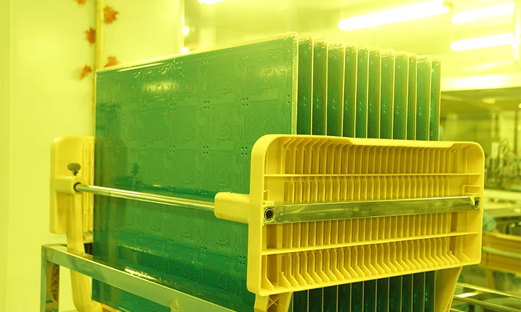
Innovations in PCB Coil Manufacturing Processes
The manufacturing of PCB coils has evolved significantly, driven by the increasing need for miniaturized, high-performance electronics. As the push for smaller and more powerful components continues, production techniques have advanced to meet these new challenges. Innovations such as improved copper etching methods enable the creation of finer, more accurate coil patterns, while flexible PCBs offer the ability to design coils in more compact and adaptable configurations. Manufacturers are constantly exploring new possibilities, testing the boundaries of what can be achieved to deliver cutting-edge solutions for industries that demand efficient, space-saving components. In this section, we’ll dive deep into these cutting-edge advancements, and show you exactly how these changes are shaping the future of PCB coil technology.
Advanced Techniques in PCB Coil Production
When it comes to PCB coil production, it’s all about precision, efficiency, and minimizing any defects that could compromise performance. A number of advanced manufacturing techniques have been developed in recent years, allowing us to produce PCB coils with better power handling, more compact designs, and higher thermal stability.
1.Copper Etching Innovations-
One of the key processes in PCB coil manufacturing is copper etching, which defines the geometry of the coils. Traditional methods involved etching with harsh chemicals, but modern techniques are far more refined. Laser etching and direct-write technology are being increasingly used to create more complex designs with fine traces. These innovations allow us to create coils with higher precision, ensuring the inductance values are spot on and the coil geometry is optimized for performance.
| Etching Method | Precision | Benefits |
| Laser Etching | High precision | Allows for intricate designs and fine trace widths |
| Direct-write Technology | Extremely fine control | No need for traditional masks, faster setup times |
| Traditional Chemical Etching | Lower precision | Lower cost, but less suitable for high-performance designs |
2.Lamination Techniques-
The lamination process is another area where innovations have made a big difference. Modern lamination technology allows for multi-layer PCBs that integrate PCB coils with higher performance characteristics. The use of high-frequency laminate materials, such as Rogers substrates, makes it possible to achieve high thermal stability and low loss in demanding environments like power conversion systems.
| Lamination Type | Benefits | Applications |
| Traditional Lamination | Cost-effective | Standard applications with moderate power demands |
| High-Frequency Laminate | Better performance at high frequencies | Used in RF systems, power converters, and telecom |
| Multilayer Lamination | Higher density, more compact | Ideal for complex PCB coil designs and miniaturized devices |
3.Via Technology-
Vias, small holes that link multiple PCB layers, are indispensable in PCB coil design. With advancements in microvia and blind via technology, we can achieve more compact coil structures that improve current distribution and thermal efficiency. This is especially beneficial in high-power applications, where managing heat and ensuring consistent performance is key. Laser-drilled vias, now widely used, offer high precision and are perfect for handling the dense, high-performance needs of modern designs. These innovations allow for more efficient use of space while keeping PCBs reliable and effective in demanding environments.
| Via Type | Performance Impact | Applications |
| Microvias | Smaller, faster currents | Ideal for high-density PCB coils |
| Blind Vias | Compact design, increased efficiency | Common in multi-layer PCBs for high-frequency applications |
| Through-Hole Vias | Simple, but less efficient | Used for general-purpose applications |
Role of Flexible PCBs in Coil Manufacturing
Flexible PCBs (FPCBs) are gaining popularity in PCB coil manufacturing, especially when we face challenges related to space and flexibility. These flexible circuits, constructed on bendable substrates, provide new opportunities, particularly in portable and wearable electronics. With the demand for smaller and more adaptable devices, FPCBs allow manufacturers to design coils that fit in tight, unconventional spaces while maintaining performance.
1.Advantages in Compact and Portable Designs-
The flexibility of these PCBs allows for designs that are much smaller and more adaptable compared to traditional rigid PCBs. Flexible PCB coils are ideal for small-form-factor electronics such as smartwatches, hearing aids, and IoT devices. As devices continue to shrink in size but increase in power, FPCBs provide the necessary physical flexibility without compromising performance. Moreover, these coils are capable of handling high-current applications, providing power to devices in challenging spaces while maintaining performance standards.
| Flexibility | Design Benefits | Applications |
| Flexible PCBs | Thin, adaptable, space-saving | Wearable electronics, portable devices, IoT |
| Rigid PCBs | Stronger, more durable | Traditional electronics, automotive, large devices |
| Hybrid Designs | Combines benefits of both | High-performance electronics with space constraints |
2.High Power Handling-
Flexible PCB coils can handle the demands of high-current applications, especially when paired with materials like polyimide or PET substrates. The thermal stability and flexibility offered by these materials are perfect for applications requiring tight geometries and significant power loads, such as medical devices and automotive electronics.
| Material | Flexibility | Current Handling |
| Polyimide | Highly flexible | Can handle moderate to high currents |
| PET (Polyester) | Less flexible but cheaper | Suitable for lower-current applications |
| Rogers Materials | Rigid and flexible | Excellent for high-frequency, high-power designs |
Quality Control Standards for PCB Coils
In high-performance PCB coil manufacturing, maintaining top-notch quality control (QC) is absolutely essential. High-power applications demand precision in inductance and reliable thermal stability, so we must adhere to strict standards to ensure each PCB coil stands up to the demands of modern electronics. Quality checks throughout the production process, from material selection to final testing, guarantee that coils can handle the heat and electrical stress of demanding environments. QC isn’t just a box to tick—it’s the foundation of reliability, ensuring that every coil works as expected under various conditions without failure.
1.IPC Standards-
The IPC (Institute for Printed Circuits) standards govern the manufacturing quality of PCBs. Following these standards guarantees that the PCB coils meet the necessary requirements for inductance accuracy, thermal performance, and current handling. IPC-2221 and IPC-6012 are the two most common standards followed in the design and manufacture of high-performance PCB coils. These standards outline requirements for layer stacking, via quality, and signal integrity.
| IPC Standard | Quality Control Focus | Impact on PCB Coils |
| IPC-2221 | Design requirements for PCBs | Ensures proper coil design, layout, and manufacturability |
| IPC-6012 | Qualification of rigid PCBs | Guarantees that the PCB can handle high power and high frequencies |
| IPC-A-600 | Visual inspection of PCBs | Ensures consistent manufacturing quality |
2.ISO Standards-
Adherence to ISO 9001 and ISO 14001 standards ensures that the PCB coil manufacturing process meets international quality assurance criteria. These standards are focused on consistent production, reducing defects, and ensuring high-level customer satisfaction. ISO certifications also guarantee that the materials used, such as substrates and copper thickness, comply with the required specifications.
| ISO Standard | Quality Control Focus | Impact on PCB Coils |
| ISO 9001 | Quality management systems | Enhances product consistency and reliability |
| ISO 14001 | Environmental management | Ensures sustainable manufacturing processes |
Challenges in Designing and Manufacturing PCB Coils
Designing and manufacturing PCB coils is no easy feat. As the demand for high-performance electronics ramps up, engineers are feeling the heat when it comes to tackling design and manufacturing hurdles. From managing excessive heat buildup to dealing with pesky high-frequency interference, there’s no shortage of roadblocks along the way. But the good news? Engineers are constantly pushing the envelope with fresh innovations and smart strategies to break down these barriers. Whether it’s new materials or more efficient designs, the industry is stepping up its game to meet the challenge head-on and keep things on track.
Overcoming Thermal Management Issues in PCB Coils
One of the biggest headaches in PCB coil design is thermal management. Power electronics are no strangers to heat, and PCB coils—which handle significant amounts of current—are often tasked with dissipating heat. If not managed properly, excessive heat can damage sensitive components, reduce efficiency, and even lead to system failure.
1.Heat Sink Designs-
To deal with this, heat sink designs have become increasingly sophisticated. Our Engineers now incorporate multi-layered designs with copper traces to spread heat more evenly across the PCB, ensuring it doesn’t concentrate in one area. The use of copper-based heat sinks and high thermal conductivity materials like graphene is a growing trend, especially in high-power applications such as electric vehicles and solar power inverters.
For instance, graphene-based heat sinks are now being tested in PCB coils to handle high currents without excessive heating. These materials help distribute heat efficiently, which is especially crucial in high-power systems like DC-DC converters where heat can rapidly become an issue.
| Heat Dissipation Method | Effectiveness | Common Applications |
| Copper Traces | Excellent thermal conductivity | High-power systems like EVs, industrial equipment |
| Graphene Heat Sinks | High efficiency, lightweight | High-performance power electronics |
| Thermal Pads | Moderate, cost-effective | Consumer electronics, IoT devices |
2.Advanced Material Integration-
Thermal vias and thermal pads are also employed to direct heat away from sensitive areas on the PCB. These materials work by creating paths for heat to travel and dissipate away from the PCB coil. Engineers are now turning to high-conductivity dielectric materials that maintain structural integrity while still allowing heat to be effectively managed.
With these innovations, the goal is clear: keep the heat down and performance up.
Addressing High-Frequency Noise in PCB Coils
High-frequency noise is another persistent issue when designing PCB coils for sensitive applications. Electromagnetic interference (EMI) and radio-frequency interference (RFI) can cause performance degradation, data corruption, and even complete failure in high-speed systems. When you’re dealing with high-current applications or multi-layer PCBs, interference can sneak in from all directions. But our engineers have a toolkit of techniques to reduce or eliminate these issues.
1.EMI/RFI Suppression Techniques-
One of the first steps in PCB coil noise suppression is shielding. Placing ground planes and copper shields around sensitive areas of the PCB can help block external interference. For higher-frequency applications, foil shields and magnetic shielding materials are employed to ensure the signal integrity of the coil is maintained.
A great example is the use of ferromagnetic alloys around the PCB to prevent unwanted signals from entering the coil’s operational space. These materials are often employed in power electronics and RF applications like telecom devices and signal amplifiers, where EMI/RFI are high risks.
| Suppression Technique | Effectiveness | Common Applications |
| Ground Planes | Effective at mid to high frequencies | Consumer electronics, low-power systems |
| Copper Shielding | Blocks both EMI and RFI | High-frequency RF circuits, data transmission |
| Magnetic Shields | Superior at ultra-high frequencies | Telecom, signal processing |
2.Layered PCB Design-
Another method to combat high-frequency noise is the layered PCB design. By increasing the number of layers in the PCB, we can create better separation between power and signal layers. This separation acts as a physical barrier to reduce noise coupling between PCB coils and nearby signal traces. Proper layer stacking is one of the most effective ways to design for noise immunity, especially in devices like wireless charging stations or RF applications.
With these measures in place, PCB coils are more likely to perform optimally in noise-sensitive environments.
Cost-Effectiveness vs. Performance in PCB Coil Production
The balance between cost-effectiveness and performance has always been a tightrope walk. On one hand, you need to make sure the PCB coils deliver top-notch performance, especially in high-power or high-frequency scenarios. On the other hand, manufacturers are constantly looking for ways to reduce production costs without compromising the integrity of the final product. So, how do you find the sweet spot?
1.Scalable Manufacturing Methods-
One way to achieve this balance is by utilizing scalable manufacturing techniques such as automated pick-and-place machines and high-throughput etching processes. These methods allow manufacturers to mass-produce PCB coils quickly and cost-effectively, without sacrificing quality. As a result, these methods are ideal for industries looking to reduce costs while scaling up production, such as consumer electronics and IoT devices.
2.Material Selection-
Material choice is also a major factor when balancing cost and performance. While high-end materials like gold-plated copper and Rogers substrates provide outstanding performance, they come with a steep price tag. On the other hand, standard copper or FR-4 substrates might not offer the same performance, but they are widely used in consumer-level electronics and low-power applications where cost-effectiveness takes precedence.
| Manufacturing Method | Cost Impact | Performance Benefits |
| Automated Pick-and-Place | Low to moderate | Increases production speed, reduces labor costs |
| High-Throughput Etching | Moderate | Reduces material waste, improves production yield |
| Manual Assembly | High | Suitable for custom, low-volume productions |
3.Performance vs. Price-
In terms of performance vs. price, the key is finding the right materials that balance both. A high-performance PCB coil might use a combination of premium copper and specialized substrates, while a more budget-friendly version might rely on standard copper and basic FR-4. By adjusting these components, we can target different market segments without losing quality.
| Material Choice | Cost | Performance |
| Gold-Plated Copper | High | Superior conductivity, low resistance |
| Copper Clad with FR-4 | Moderate | Affordable, good for general-purpose designs |
| Rogers Substrate | High | Excellent for high-frequency and high-power designs |
How Testing and Validation for PCB Coils?
When it comes to PCB coils, effective testing and validation are non-negotiable. These tests ensure that the coils meet the required standards for performance, durability, and reliability across diverse applications. Whether it’s a high-current automotive system, a medical imaging device, or an industrial power supply, precise validation guarantees that the coils function as expected throughout their lifespan. Here’s a deep dive into the key steps and technologies involved in validating PCB coils for optimal performance.
Key Performance Tests for PCB Coils
To ensure a PCB coil performs under the most demanding conditions, we rely on a range of performance tests that measure key attributes such as impedance, inductance, and thermal stability. These tests provide critical insights into the coil’s behavior under operational stress and its ability to meet industry standards.
1.Impedance Testing-
Impedance is a critical parameter that affects how the coil interacts with alternating current (AC) signals. High-precision impedance analyzers are used to measure the resistance to current flow, ensuring that the coil is tuned to the correct specifications. In high-frequency applications, like RF circuits, impedance mismatches can cause signal reflections and loss of power, leading to inefficiencies. Through impedance testing, designers can fine-tune the coil’s geometry and materials to optimize signal integrity and minimize loss.
2.Inductance Measurement-
Inductance refers to a coil’s ability to store energy in a magnetic field, and it’s measured using LCR meters (which check inductance, capacitance, and resistance). This measurement helps ensure the coil delivers the right inductive reactance needed for a specific circuit. Inductance testing is a must-do when confirming that the coil matches power conversion, filtering, or signal processing specs. Without it, you could run into issues with energy storage or interference, especially in applications like power electronics or energy storage systems. By keeping inductance in check, we can make sure everything stays up to snuff.
3.Thermal Stability Testing-
The performance of a PCB coil can degrade if it becomes too hot. Thermal stability testing is used to assess the temperature tolerance of a coil and its ability to maintain efficiency and functionality under heat stress. Advanced thermal cameras and oven testing simulate extreme operating temperatures to validate the coil’s design. Thermal cycling is a key aspect of stress testing, especially in automotive and industrial applications where coils must perform under extreme environmental conditions.
| Test Type | Purpose | Tools Used | Target Application |
| Impedance Testing | Measures resistance to alternating current | Impedance analyzers | RF circuits, high-frequency systems |
| Inductance Measurement | Verifies energy storage capacity | LCR meters | Power conversion, filtering |
| Thermal Stability | Assesses performance under temperature extremes | Thermal cameras, oven testing | Automotive, industrial, medical |
Tools and Software for PCB Coil Simulation
The design and validation process of PCB coils is made easier with the use of advanced simulation software. These tools allow our engineers to virtually test various coil designs, optimizing for factors like efficiency, size, and power handling before physical testing. By simulating the coil’s behavior in different operating conditions, designers can quickly identify potential issues and refine their designs.
1.CAD Tools for Prototyping-
Computer-Aided Design (CAD) tools are indispensable when it comes to creating precise PCB coil layouts. These software solutions, like Altium Designer, Autodesk Eagle, and KiCad, provide engineers with the ability to visualize and adjust coil geometry with pinpoint accuracy. Whether it’s optimizing coil placement or adjusting intricate designs to fit within the constraints of the PCB, these tools give engineers the flexibility to ensure everything is spot on. With CAD, you can take a complex coil design and refine it to perfection, making sure it performs just as it should without compromising space or functionality.
2.Electromagnetic Simulation-
Once the design is complete, electromagnetic (EM) simulation tools like Ansys HFSS or COMSOL Multiphysics are used to simulate how the coil behaves in a circuit. These tools predict the electromagnetic field distribution, current density, and thermal performance of the PCB coil, enabling we to avoid potential signal interference, power loss, or thermal runaway. They also help in assessing the inductance and resonant frequency of the coils, ensuring that they meet application-specific needs.
| Tool Type | Purpose | Popular Tools | Application Areas |
| CAD Tools | Design and layout of PCB coils | Altium Designer, KiCad, Autodesk Eagle | PCB design, coil geometry optimization |
| EM Simulation Software | Electromagnetic field analysis and performance prediction | Ansys HFSS, COMSOL Multiphysics | RF circuits, power electronics |
| Thermal Simulation Tools | Predicts coil performance under varying temperature conditions | FloTHERM, COMSOL, Thermal Desktop | Thermal management, heat dissipation |
Ensuring Longevity and Reliability in PCB Coil Applications
The long-term performance and reliability of a PCB coil depend not only on its initial design but also on how it holds up under stress testing and life-cycle evaluations. These testing procedures simulate real-world conditions that the coil will face throughout its service life, ensuring it meets the demands of its specific application, whether in a high-power industrial setting or a sensitive medical device.
1.Stress Testing Under Extreme Conditions-
Stress testing for PCB coils involves subjecting the coils to extreme conditions, such as high temperatures, rapid thermal cycling, mechanical vibration, and electrical overstress. Automotive or aviation applications, for instance, require coils to endure not just heat but also vibration from constant movement. Accelerated life testing pushes the coils to their limits to determine their failure points and predict how long they will last in real-world usage.
2.Lifecycle Assessments-
Engineers perform lifecycle assessments to evaluate how the coil performs over time under continuous operation. These tests take into account factors like fatigue and material degradation, ensuring that the coil can handle wear and tear over an extended period. For medical devices, where reliability is non-negotiable, these assessments become even more stringent, as failure could lead to costly repairs or, in the worst case, harm to patients.
| Testing Type | Purpose | Common Tools | Industries |
| Stress Testing | Simulates extreme operating conditions | Thermal chambers, vibration testers | Automotive, aerospace, industrial |
| Lifecycle Assessment | Predicts coil behavior over extended operational periods | Accelerated life test chambers | Medical, heavy machinery, power systems |
PCB Coil Solutions for Specialized Industries
PCB coils are playing a transformative role in industries where performance, precision, and efficiency are non-negotiable. From automotive systems demanding robustness to the delicate needs of medical devices and the heavy-duty requirements in industrial machinery, PCB coils are being customized to meet the unique challenges of each sector. Let’s explore how these coils are tailored for specialized applications, delivering exceptional performance across industries.
Customized PCB Coils for Automotive Applications
In the automotive industry, PCB coils are a cornerstone in building small, high-performance systems that power today’s vehicles. From electric vehicles (EVs) to advanced driver-assistance systems (ADAS), automotive electronics require reliable, efficient, and compact components. PCB coils in these applications are designed with a focus on EMI shielding and high-current capacity, both of which are critical for ensuring the safe and efficient operation of electronic systems.
1.EMI Shielding in Automotive Systems-
Modern vehicles are increasingly packed with sensors, communication systems, and high-performance electronics that can suffer from interference. PCB coils used in these applications are custom-designed with built-in electromagnetic interference (EMI) shielding, which prevents disruptions to sensitive components. For example, EV powertrains require coils that manage high-current levels while also shielding power systems from noise that could affect motor control or battery charging systems.
2.High-Current Systems-
One example of high-current PCB coils in automotive applications can be found in the DC-DC converters used for electric vehicle (EV) charging systems. These coils are engineered to handle power surges and voltage fluctuations while maintaining steady efficiency. By integrating the coils directly into the PCB, we are able to conserve valuable space and improve overall system performance, a must in tight spots like electric drive motors and onboard power supplies. This design approach not only optimizes space but also ensures that power conversion happens seamlessly, even under heavy load conditions, helping EV systems keep the wheels turning without a hitch.
| Automotive Application | PCB Coil Features | Performance Benefits |
| EV Powertrains | High-current, EMI shielded | Reliable power delivery with reduced interference |
| Advanced Driver Assistance Systems (ADAS) | Compact, noise-resistant coils | Enhanced sensor accuracy and signal integrity |
| Onboard Power Supplies | High-efficiency coils | Smaller, efficient power conversion for charging systems |
PCB Coils in Medical Devices
In the medical field, PCB coils are designed to meet stringent requirements of precision, reliability, and biocompatibility. These coils are typically used in imaging systems, diagnostic devices, and monitoring systems, where even the smallest error can lead to inaccurate results. The high precision required in medical applications demands careful consideration of factors like inductance, tolerance, and overall component integrity.
1.High-Precision Inductors-
In medical devices like MRI systems and ultrasound machines, PCB coils are at the heart of precision signal processing. These devices rely on the flawless generation and reception of electromagnetic signals, and that’s where high-precision inductors come in. Engineers meticulously design these coils using top-notch materials and advanced shielding methods, ensuring they stay as noise-free as possible. This careful design process minimizes interference, allowing for clear and undistorted images during the scanning process. It’s like fine-tuning a high-end instrument to get the sharpest sound—it’s all about eliminating any unwanted noise and keeping the focus on what matters: accurate imaging.
2.Imaging Systems and Diagnostics-
In MRI and CT scanners, PCB coils play a double role—functioning as both radiofrequency (RF) coils and gradient coils, each performing a specific task that contributes to the precision of body scans. The RF coils are tasked with capturing signals from the body, while the gradient coils shape the imaging field to produce detailed, high-resolution images. These coils are crafted with high-grade copper and fiberglass substrates, materials chosen to maintain the integrity of the signal while handling the high-powered currents that are a core part of the imaging process. It’s like having the right tools to get the job done without any breakdowns—keeping things running at full capacity for accurate and dependable results.
| Medical Application | PCB Coil Features | Performance Benefits |
| MRI Systems | High-precision, noise-free coils | Clear, accurate imaging with minimal interference |
| Ultrasound Devices | Compact, low-profile coils | Accurate diagnostics in confined spaces |
| Diagnostic Equipment | Stable inductance, high tolerance | Reliable performance in critical, life-saving devices |
Industrial Applications of PCB Coils
In heavy machinery and robotics, PCB coils serve as the backbone of power electronics, ensuring smooth operation and high reliability. These industries demand high-performance solutions that can handle heavy-duty tasks in harsh environments, while maintaining high efficiency and minimal downtime. Whether in industrial robots or large-scale manufacturing equipment, PCB coils are designed to meet these extreme demands.
1.High-Power Applications in Robotics-
In industrial robotics, PCB coils are used in motion control systems and servo motors to handle high currents and ensure precise movement. These systems require high-performance inductive components capable of withstanding the stresses of constant operation without overheating or losing efficiency. Our Engineers often integrate thermal management techniques like multi-layer PCBs and heat sinks into the design to keep the coils operating within optimal temperature ranges.
2.Heavy Machinery-
For industrial machinery, PCB coils are often used in systems like variable-frequency drives (VFDs) and transformers. These devices manage high power loads and regulate machinery speed, making the coil design essential for power distribution and system control. To prevent failure in these mission-critical systems, PCB coils are designed with materials that provide high durability and low resistance, such as copper-clad laminates.
| Industrial Application | PCB Coil Features | Performance Benefits |
| Robotics | High-current, thermal management | High precision and efficiency in motion control |
| Heavy Machinery | High-durability, low-resistance | Reliable power delivery in demanding industrial settings |
| Variable Frequency Drives | Low-profile, high-efficiency coils | Efficient power regulation for machinery operation |
Why Choose JarnisTech as Your Trusted PCB Coil Supplier in China?
JarnisTech is committed to delivering top-notch coil PCBs tailored to meet the ever-evolving needs of the global electronics market. With a robust manufacturing capacity and a customer-first philosophy, we excel in providing solutions that combine innovation, reliability, and precision engineering.
●Comprehensive Manufacturing Capabilities
From single-layer designs to intricate 24-layer coil PCBs, JarnisTech ensures that every product meets exacting quality standards. Our production process is designed to handle orders of any size, from small-scale prototypes to high-volume manufacturing runs, with equal dedication to precision and efficiency.
| Specification | Capability | Benefits |
| Layer Count | 2–24 Layers | Versatility for complex applications |
| High-Speed Capacity | Up to 20Gbps | Ideal for advanced signal integrity |
| Heat Management Options | Integrated heat sinks | Enhanced reliability under load |
●Tailored Technical Assistance Around the Clock
Our technical team is available 24/7, ready to assist with custom applications that demand precision solutions, such as high-speed data transmission, compact designs, or high-frequency applications. For instance, one of our clients needed a compact PCB for an aerospace project, and we delivered a high-capacity design with a press-fit heat sink that met stringent space and performance criteria.
●Free Design Support and Manufacturing Analysis
We offer complimentary Design Rule Check (DRC) and Design for Manufacturability (DFM) evaluations to streamline the transition from design to production.
| Service | Details |
| Layout Panel Review | Optimization for production efficiency |
| Impedance Design Guidelines | Ensures high-speed signal integrity |
| Material Selection Advice | Helps in choosing cost-effective, durable options |
●Customer-Focused Problem Solving
We don’t just build PCBs—we collaborate with you to create solutions that work. From selecting the ideal substrate to advising on microvias or gold plating for enhanced conductivity, our goal is to maximize the value of your investment.
For example, a client working on IoT devices benefited from our guidance on specific laminates, reducing overall thickness and improving signal integrity without increasing costs.
●Global Reach with a Local Touch
With experience in shipping to international electronic markets, JarnisTech understands the unique requirements of different regions. Whether you’re in the US, Europe, or Asia, we ensure timely delivery and compliance with regional standards.
●Proactive Quality Assurance
Every PCB is rigorously tested for performance, including inductance, impedance, and thermal stability. This commitment to quality ensures longevity and reliability in even the most demanding applications.
●Our Capabilities in Manufacturing Coil PCB
| Category | Specification |
| Monthly Capability | 15,000 m²/month |
| Layer Count | 2-24 Layers |
| Material Options | FR4, TG140, TG170, etc. |
| Maximum Dimensions | 310.18mm x 140.25mm |
| Outer Layer Finished Board Thickness | 1oz, 2oz, 3oz, etc. |
| Inner Layer Base Copper Thickness | 1oz, 2oz, 3oz, etc. |
FAQ & PCB Coil
How do I calculate the inductance of a PCB coil?
Inductance depends on factors such as the number of turns, trace width, spacing, and substrate properties. Tools like online calculators or electromagnetic simulation software can simplify this process.
What materials are commonly used in PCB coils, and why?
Copper is the preferred material due to its excellent conductivity. Substrates like FR4 or high-frequency laminates are chosen based on application-specific thermal and electrical requirements.
How can I improve the efficiency of a PCB coil in high-frequency applications?
Efficiency can be enhanced by optimizing trace geometry, using high-quality substrates, and minimizing parasitic capacitance and resistance through careful layout design.
Are there specific design standards for PCB coils used in medical or automotive applications?
Yes, standards such as ISO 13485 for medical devices and IATF 16949 for automotive electronics outline performance and safety criteria, including thermal stability and EMI compliance.
What are the limitations of PCB coils compared to other inductor types?
PCB coils may have lower current-handling capability and higher losses due to thinner traces, making them less suitable for high-power applications without additional design considerations.
Can PCB coils be designed for flexible PCBs?
Yes, flexible PCBs can incorporate coil designs for applications that demand lightweight, compact, and bendable solutions, such as wearable devices and aerospace electronics.
What is the impact of high-frequency operation on PCB coil performance?
At high frequencies, skin effect and proximity effect increase resistance, reducing efficiency. Mitigation strategies include using wider traces or Litz wire techniques.


