Printed circuit boards (PCBs) serve as the backbone of all electronic devices, providing a means of connecting various circuit components together in a consistent and reliable manner. While PCBs may not be as flashy as microprocessors or as ubiquitous as resistors, they are nonetheless a crucial component in the design and production of electronic devices.
At JarnisTech, we are passionate about PCB design and believe that this skill is of great benefit to electronics enthusiasts of all levels. To this end, we have created a series of tutorials to teach you the fundamentals of Eagle PCB design.
Before delving into the specifics of Eagle PCB design, it is important to understand why this software is an excellent choice for your PCB design needs. Eagle offers a multitude of features and benefits that make it an indispensable tool for creating high-quality PCB designs. By utilizing Eagle, you can streamline your design process and produce reliable and efficient PCBs with ease.
We are excited to share our knowledge and expertise in Eagle PCB design with you, and look forward to helping you develop your skills in this important area of electronics engineering.
What Is Eagle PCB ?
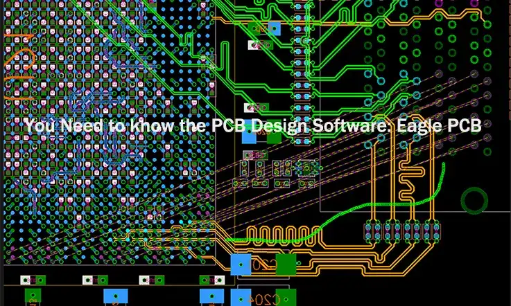
Eagle PCB (Printed Circuit Board) is a software tool used for designing and creating electronic circuit boards. It is a popular software package developed by Autodesk that allows users to create schematics and layouts for printed circuit boards.
Eagle PCB is commonly used by engineers, designers, and hobbyists for designing and prototyping electronic circuits. The software provides a user-friendly interface that includes a schematic editor, a PCB layout editor, and a library editor.
Using Eagle PCB, users can create and edit electronic circuits, add components, and connect them using wires and traces. The software also provides a wide range of features such as autorouting, design rule checking, and schematic capture.
Eagle PCB allows users to export their designs in various file formats, including Gerber files for manufacturing. It can also be integrated with other software tools such as SPICE simulation software and 3D CAD software to enhance the design process.
Getting Started with Eagle PCB
Here’s an overview of getting started with Eagle PCB:
1. Download and Install Eagle PCB: You’ll need to download and install the Eagle PCB software from the Autodesk website. Follow the installation instructions provided on the website to complete the installation process.
2. Launch Eagle PCB: Once you’ve installed Eagle PCB, launch the software by double-clicking on the application icon.
3. Create a New Project: In Eagle PCB, a project is a container for all the files related to a specific design. To create a new project, go to the File menu and select New > Project. Enter a name for your project and choose a location to save it.
4. Add Components to a Schematic: In Eagle PCB, you’ll start by creating a schematic of your design. To add components to your schematic, select the Add Part tool from the toolbar and click on the schematic editor where you want to place the component. You can also search for components in the Eagle PCB library and add them to your design.
5. Connect Components on a Schematic: To connect components on a schematic, use the Net tool to draw wires between the pins of your components. You can also use the Bus tool to connect multiple wires together.
6. Generate a Netlist: Once you’ve created your schematic, you’ll need to generate a netlist. This is a list of all the components in your design and how they’re connected. To generate a netlist, go to the File menu and select Export > Netlist. Choose a location to save your netlist file.
7. Create a Board Layout: With your netlist file, you’ll now create a board layout in Eagle PCB. Go to the File menu and select New > Board. Eagle PCB will import your netlist and create a board with all the components and connections from your schematic.
8. Place Components on a Board: In the board layout editor, you’ll need to place your components on the board. Use the Move tool to drag components into position.
9. Route Connections on a Board: With your components placed, you’ll need to route the connections on your board. Use the Route tool to draw traces between your components.
10. Generate Gerber Files: Once you’ve completed your board layout, you’ll need to generate Gerber files. These are the files used to manufacture your PCB. To generate Gerber files, go to the File menu and select CAM Processor. Choose a location to save your Gerber files and follow the instructions provided by Eagle PCB.
That’s a brief overview of getting started with Eagle PCB. There are many more features and tools available in the software, so it’s worth exploring the documentation and tutorials to get the most out of it.
How Does Eagle PCB Function ?
Eagle PCB design software utilizes electronic design automation to enable circuit designers to perform multiple operations simultaneously. The software is designed using the model interface method, allowing for efficient and effective PCB design.

The software is composed of several key views, including the Control Panel, Library, Schematic, and Board Layout. The Control Panel serves as the primary window for controlling the various functions of the software and launching other windows.
The Eagle PCB library is a rich and versatile resource that provides a wide range of design tools to optimize the PCB design process. It allows designers to edit and regulate the functionalities of parts and components, ensuring that they meet the specific needs of the project.
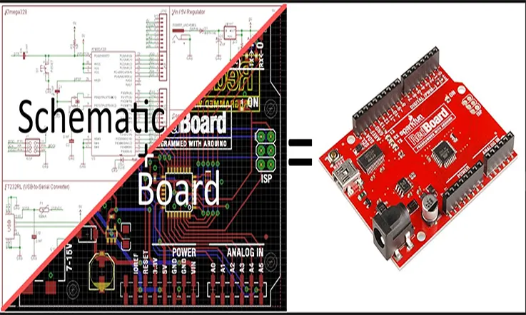
The Schematic view is where designers place the PCB components and connect the pins to their designated segments. This view defines the parts and their connections, with components typically placed according to electrical considerations.
Finally, the Board Layout view is where designers place their project and connect it in accordance with the schematics. Here, parts are connected in a way that makes physical sense. The Board Layout view is critical in ensuring that the final PCB design is both functional and practical.
Why Choose the Eagle PCB Design Software ?
Eagle PCB Design Software is a popular and highly-regarded PCB CAD software that offers a range of unique and beneficial features. Below are some of the reasons why Eagle PCB Design Software is an excellent choice for circuit designers:
User Interface: Eagle PCB has a highly customizable user interface that allows users to create custom toolbars, hotkeys, and scripts. This makes it easier for users to work efficiently and customize the software to their needs.
Library Parts: Eagle PCB has a large library of components and footprints that users can use in their designs. The library is continually updated with new parts and is maintained by the software developer, Autodesk. In addition, users can create their own custom library parts.
Lightweight: Eagle requires a minimal amount of disk space ranging from 50 to 200 MB, as compared to other advanced tools that may require over 10 GB. Its installer is also compact, at approximately 25 MB, allowing for quick and easy installation within minutes.
Cross-Platform: Eagle is a cross-platform software that can run seamlessly on Linux, Mac, and Windows, making it highly versatile and accessible to designers across multiple operating systems.
Community Support: Eagle enjoys a strong and supportive community of PCB designers who appreciate its functionality and user-friendly interface. This community means that designers can easily access a wealth of knowledge and resources, including pre-existing designs of popular components and circuit boards.
Simulation: Eagle PCB has a built-in simulation tool called SPICE that allows users to simulate the behavior of their circuits before building them. This can help users identify potential problems and optimize their designs.
3D Modeling: Eagle PCB has a built-in 3D modeling tool that allows users to visualize their designs in 3D. This can help users check for mechanical interference and visualize how their components will fit together.
Collaboration: Eagle PCB doesn’t have built-in collaboration tools, which can make it difficult to collaborate on designs with others. However, it does support exporting designs in various formats, which can be shared with others who use different PCB design software.
Low or Free Cost: Eagle offers a freeware version that provides sufficient utility for designing most printed circuit boards. However, for those who need more advanced features, upgrading to a higher plan is relatively inexpensive compared to other high-end tools, making it an affordable option for both hobbyists and professionals.
Overall, Eagle PCB Design Software is an excellent choice for designers looking for a lightweight, cross-platform, cost-effective solution that is backed by a supportive community.
What Are The Limitations Of Eagle PCB ?
As with any software, Eagle PCB has its limitations. Here are some of the most common limitations of Eagle PCB:
Limited Free Version: The free version of Eagle PCB has some limitations, such as a limited board size and limited number of schematic sheets. If you need to create larger or more complex designs, you’ll need to purchase a license for the full version.
Limited Library Parts: While Eagle PCB has a large library of components and footprints, it may not have every component you need. You may need to create your own custom parts or search for third-party libraries.
Limited Routing Options: Eagle PCB has a limited set of routing options, which may not be sufficient for complex designs. You may need to manually route connections or use a third-party routing tool.
Limited 3D Modeling: While Eagle PCB has a built-in 3D modeling tool, it’s not as advanced as some other 3D modeling tools. You may need to use a separate 3D modeling tool to create more complex 3D models.
Limited Simulation Options: While Eagle PCB has a built-in simulation tool called SPICE, it’s not as advanced as some other simulation tools. You may need to use a separate simulation tool to simulate more complex circuits.
Steep Learning Curve: Eagle PCB has a steep learning curve, especially for beginners. It can take some time to learn how to use all of the features and tools in the software.
Limited Collaboration Options: Eagle PCB doesn’t have built-in collaboration tools, which can make it difficult to collaborate on designs with others. You may need to use a separate collaboration tool or share files manually.
These are some of the most common limitations of Eagle PCB. However, despite its limitations, Eagle PCB is still a popular and powerful PCB design tool used by many professionals and hobbyists.
How to Check The Design Rules In Eagle PCB ?
Design rules are a crucial aspect of Eagle PCB design as they ensure that schematics are error-free and that the end product is of high quality. The design rule checks (DRCs) in Eagle software play a vital role in ensuring that design rules are adhered to and that any errors are identified.
When accessing the DRC dialog box in Eagle software, there are several tabs that you can navigate to set and check your design rules. These tabs include:
File: This section contains downloadable .drc files that can be used to check the design rules.
Layers: Depending on your version of Eagle, you may be able to check the designs of multiple layers.
Clearance: This tab allows you to set the minimum distance between different components used on the circuit board design.
Distance: Here, you can set the drill hole diameter, copper trace thickness, and other relevant dimensions.
Sizes: You can set the minimum size of drill bits and different micro and blind PCB vias.
Restring: This tab controls the dimensions of through-hole vias.
Shapes: Here, you can set the design rules for PCB pads with round edges.
Supply: This tab controls the dimensions of thermal vias used in the PCB traces.
Masks: This tab controls the use of masks on required positions of the PCB.
Misc: Here, you can check various parameters such as the grid, angle, restrict, font, etc.
Once you have completed the required tabs, you can start checking your design. One benefit of using Eagle PCB Design Software is that designers do not need to interfere with the design while checking it. Additionally, Eagle PCB crack can be utilized to further aid the design process. However, it is important to note that using cracked versions of software is illegal and can lead to various issues, including security risks and legal consequences.
Conclusion
Eagle PCB is a powerful and popular PCB design software that has many features and capabilities. It has a highly customizable user interface, a large library of components and footprints, a built-in simulation tool, and a 3D modeling tool. While it has some limitations, such as a limited free version and limited collaboration options, it’s still a popular choice for hobbyists and small projects. Choosing the right PCB design software ultimately depends on the user’s needs, preferences, and budget, but Eagle PCB is definitely worth considering for those looking for a powerful and affordable PCB design tool.
In a word, Eagle PCB is a highly regarded software that promotes the manufacturing quality of printed circuit boards, thanks to its numerous outstanding features and user-friendly interface. It has become a popular circuit solution for designers in the present day.
At JarnisTech, we specialize in researching, manufacturing, developing, and supplying Eagle PCBs with unmatched reliability. We are committed to providing comprehensive information about PCB design through this FAQ guide and are available to assist with any PCB-related issues you may encounter. Stay connected with us for updates and the latest developments in PCB design.
Related Posts:
1. Everything You Should to Know on Altium PCB Design Software
2. Which One Are the Best Auto-route PCB Software?
3. PCB Traces: The Critical Role of Traces in PCB Design and Manufacturing
4. ExpressPCB Design Tool: A Comprehensive Guide to Using ExpressPCB
5. Avoid These 5 Common PCB Design Mistakes
7. Kicad PCB: How to Understand It?
8. What Is the Difference Between Altium and Eagle?
9. How to Make a Arduino PCB – You Must to know Everything About It
10. EDA Design Software: Definition, Kinds and Important