
Flexible Printed Circuits have emerged as one of the most dynamic innovations in the electronics industry, providing engineers with the versatility and performance needed for modern electronic applications. In this guide, we’ll take you through everything you need to know about flexible PCBs, including design, manufacturing, assembly,prices and Cost, while leveraging industry insights and knowledge from leading experts.
Introduction to Flex PCB
What is a Flex PCB and How Does it Work?
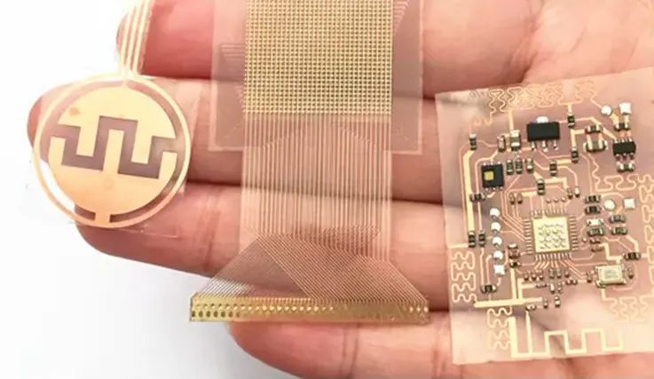
Flexible printed circuit boards (also known as flex PCBs) are circuits that bend and flex to fit into various designs. Unlike traditional rigid PCBs, flex PCBs are designed with flexible substrates that allow the board to bend, fold, and twist without compromising its electrical performance. These boards typically use a thin, flexible polymer material like polyimide (PI) or PET as their base, combined with copper traces to carry electrical signals.
How Does a Flex PCB Work? A flexible PCB works in much the same way as traditional PCBs, with one major difference: its ability to be bent and shaped without breaking. The thin substrate allows the circuitry to remain intact as it flexes. The board still contains conductive pathways—usually copper traces—on the flexible substrate, but it is built to withstand repetitive bending and movement. This makes flex PCBs ideal for applications where space is limited and parts need to move, such as in wearable devices or medical equipment.
The construction of a flex PCB typically involves layering flexible materials such as polyimide and adhesives to form a functional board. The inner layers carry the electrical traces, and the outer layers may have a solder mask to protect the traces. A coverlay is often applied to the surface to shield the circuit and components from environmental damage.
In addition to their durability, flex PCBs are typically more lightweight than traditional rigid boards, making them ideal for portable electronics and devices where minimizing size and weight is a major factor.
| Component | Material Used | Function |
| Substrate | Polyimide or PET | Provides flexibility and support to the PCB |
| Copper Traces | Copper (typically) | Carries electrical signals |
| Coverlay | Polyimide or Acrylic | Protects the traces from environmental damage |
| Solder Mask | Epoxy or Polyurethane | Shields the copper traces from oxidation |
Advantages of Using Flex PCB in Modern Electronics
When you’re designing electronic products today, you want to squeeze as much out of every square inch as you can. And that’s where flex PCBs come in. These flexible boards provide some real advantages that help manufacturers meet the growing demands of modern electronics.
Space and Weight Savings-
First off, flex PCBs offer amazing space-saving properties. Think about the design of a smartphone, a wearable, or a drone—all of these require lightweight, compact solutions. Flex PCBs let you eliminate the need for bulky connectors and wires by allowing the circuit to fold or wrap around components within tight spaces. This flexibility can make all the difference in the size and weight of the finished product, helping electronics manufacturers squeeze more functionality into smaller and lighter packages.
Flexible Designs-
Another perk? You get a lot more design freedom with flex PCBs. Their ability to be shaped and bent means you can create custom-fit, 3D forms that are difficult or even impossible to achieve with rigid boards. This opens the door for designs that could never be built using traditional methods, like complex shapes for medical devices or wearable electronics that need to move with the body.
Enhanced Durability-
Unlike traditional boards that can crack under pressure, flex PCBs are more resistant to mechanical stress. They can handle bending and twisting without breaking, making them highly durable in demanding environments, such as those in automotive or industrial applications. If your product needs to survive harsh conditions—think of an electronic component installed in a drone or a wearable device that’s constantly moving—flex PCBs are the way to go.
Key Advantages of Flex PCB-
| Advantage | Benefit | Example Application |
| Space Efficiency | Reduces the need for bulky connectors and wires | Wearable tech, Smartphones |
| Durability | Withstands bending, twisting, and wear | Medical devices, Automotive |
| Design Flexibility | Enables custom shapes and 3D configurations | Implantable medical devices |
Key Applications of Flex PCB in Different Industries
Wearables and Medical Devices-
In the wearable technology industry, flex PCBs are absolutely indispensable. Whether it’s a fitness tracker, smartwatch, or hearing aid, flex PCBs help keep these devices small, lightweight, and comfortable to wear. Thanks to the bending and folding abilities of flex PCBs, they can be integrated seamlessly into devices that conform to the body’s shape. For example, smartwatches use flexible circuits to fit snugly around the wrist without feeling bulky.
Flex PCBs are a natural fit for medical devices, where compactness and reliability are non-negotiable. From powering pacemakers to supporting hearing aids and other implantable technologies, these circuit boards enable engineers to design ultra-miniature systems. Their ability to bend and conform makes them indispensable in creating tools that operate seamlessly within the human body, especially in high-stakes settings like surgical procedures. With flex PCBs, medical technology can push boundaries, delivering devices that are not just functional but also streamlined and efficient.
Automotive Applications-
The automotive industry has been quick to adopt flex PCBs for various applications, from sensor systems to automotive lighting and battery management systems. These circuits can be designed to fit into tight spaces within a vehicle, reducing weight and improving the overall performance of electronic components. Additionally, flex PCBs can handle extreme environmental conditions, such as heat and vibration, which are common in automotive applications.
Consumer Electronics-
Consumer electronics such as smartphones, tablets, and laptops have been using flex PCBs for years. In these devices, flex PCBs provide enhanced connectivity between different parts of the product. For instance, the flexible circuit used to connect the touchscreen to the mainboard can bend and move along with the device, reducing wear and tear over time. Flexible PCBs also help reduce the size of components and ensure high-density circuit designs that are perfect for modern electronics.
| Industry | Application | Benefit of Flex PCB |
| Wearables | Fitness trackers, smartwatches | Small, lightweight, and flexible |
| Medical Devices | Pacemakers, hearing aids | Compact, reliable, and durable |
| Automotive | Sensor systems, battery management | Heat-resistant, vibration-proof |
| Consumer Electronics | Smartphones, tablets, laptops | Space-saving, high-density design |
Flex PCB Design: Key Considerations for Success
When you’re stepping into the world of flex PCB design, you’re not just making a circuit board. You’re crafting the backbone of innovative tech that’s flexible, reliable, and ready to go the distance. Designing flex PCBs requires a unique mindset and a whole new set of design rules. From the materials you choose to the way you lay out the circuit paths, flexible circuits bring a whole different level of thinking to the table. Let’s dive into what makes designing these boards so important and how to get it right from the start.
Essential Design Principles for Flex PCB
So, you want to get your flex PCB design just right? Here’s the lowdown on Design for Manufacturability (DFM), which is your best friend when designing these types of circuits. If you want to avoid headaches later on, starting with a good foundation in DFM will save you time, money, and a lot of frustration.
A flex PCB layout needs to be more than just neat and tidy. You’ve got to think about the bend. Unlike rigid boards, flex PCBs will be bent, twisted, or folded, so the trace width, component placement, and via types all need to be considered with that flexibility in mind.
In other words, don’t just throw traces wherever you like. The placement of your traces and vias needs to account for potential bending and the mechanical stress the PCB will undergo. That means using wider traces for higher currents and ensuring there’s plenty of room for flexible areas.
Design for Manufacturability (DFM) Considerations-
| Design Element | What to Watch Out For | Design Tip |
| Trace Width | Must be wide enough for current handling | Use wider traces for higher current areas |
| Component Placement | Avoid placing components near bend zones | Keep critical components away from bends |
| Via Types | Via holes weaken the flexibility of the board | Use blind or buried vias when possible |
| Copper Layer Thickness | Thin copper layers can improve flexibility | Choose thinner copper for better flexibility |
Material Selection for Flex PCB Design
You don’t just grab any old material when designing flex PCBs—you’ve got to pick the right stuff that’ll stand up to the test of time and wear. Let’s talk about the materials that make it all happen.
Polyimide stands out as the material of choice for flexible PCBs, thanks to its durability, adaptability, and excellent heat tolerance. It’s the workhorse you want when your design demands both flexibility and thermal resilience. Other contenders, like PET (polyethylene terephthalate), offer benefits for specific use cases, but polyimide remains unmatched for handling challenging environments. Therefore, don’t just go for the material because it looks nice—consider things like thermal conductivity, chemical resistance, and mechanical properties to ensure your PCB can handle the wear and tear it’s going to experience.
Then, there’s the copper type. The copper has to be able to handle electrical conductivity but still remain flexible. Oxygen-free copper (OFC) is ideal for high-quality electrical connections and longevity. Meanwhile, for applications like high-frequency circuits, you’ll want to consider hydrocarbon-based materials that can help reduce signal loss.
Material Choices for Flex PCB-
| Material | Key Features | Common Uses |
| Polyimide | Flexible, heat-resistant, durable | Used for flexible and rigid-flex PCBs |
| PET (Polyethylene Terephthalate) | Cost-effective, flexible, good mechanical strength | Used in consumer electronics |
| Oxygen-Free Copper (OFC) | High conductivity, long-lasting | Ideal for high-power applications |
| Hydrocarbon-Based Materials | Lower signal loss, good for high-frequency circuits | Used in RF applications and high-speed data transmission |
Common Design Challenges in Flex PCB Layouts
Alright, you’ve mastered the basics, so let’s peel back the curtain on the real-world hurdles of designing flex PCBs. This isn’t exactly child’s play—it’s more like solving a complex puzzle with a few twists and turns.
Flex PCBs bring with them a unique set of challenges, and if you’re not paying close attention to the finer details, you could end up with a design that’s more rigid than flexible. It’s not just about getting the bends right; it’s about ensuring that every layer, trace, and material choice works together seamlessly. Ready to dig deeper and tackle these challenges head-on? Let’s get into the weeds and make your designs as solid as they are versatile.
One of the most common issues in flex PCB layout is managing the bending radius. If you bend the board too tightly, you can cause the traces to break or the substrate to crack. The trick is to calculate the bend radius—this is the minimum radius you can bend the PCB without damaging it. The general rule is that the bend radius should be at least 10 times the thickness of the PCB.
Another hurdle is maintaining electrical conductivity when the PCB is bent. Solder joints can weaken with repeated bending, so flex PCBs need to be designed with stress-relief zones at critical points to prevent failure.
Last but definitely not least, there’s the mechanical stability. Since flex PCBs are often subjected to physical movement or stress, the design needs to stand up to mechanical force without compromising on electrical performance. It’s a balancing act of making the board flexible, yet durable enough to handle the strain.
Common Challenges in Flex PCB Design-
| Challenge | What to Watch Out For | Solution |
| Bending Radius | Too tight of a bend can damage the PCB | Ensure the bend radius is at least 10x the thickness of the PCB |
| Electrical Conductivity | Solder joints weaken with bending | Use stress-relief zones and stronger materials |
| Mechanical Stability | Excessive physical stress can lead to failure | Design with durability and flexibility in mind |
Manufacturing Flex PCB: Process and Best Practices
When you’re diving into the world of flex PCB manufacturing, you’re entering a space where precision, cutting-edge technology, and a sharp eye for detail all come together. Unlike traditional rigid PCBs, flex boards need careful attention to material handling, layer alignment, and manufacturing processes that allow them to bend and twist without compromising their function. Let’s take a deeper dive into how flex PCBs are made, the best practices to keep in mind, and how to tackle some of the toughest challenges on the manufacturing floor.
The Step-by-Step Manufacturing Process of Flex PCB
Making flex PCBs is no quick-and-dirty job—it’s a methodical process with precise steps to ensure every layer and connection meets the mark. Think of it as crafting a masterpiece where each phase builds on the previous one to deliver a functional and durable circuit. Here’s how it typically goes down in the manufacturing world:
1.Material Preparation: The process kicks off with the selection and preparation of the flexible substrate—most commonly polyimide. This material offers flexibility and high thermal stability, ensuring your circuit performs under extreme conditions. It’s cut into the right size based on the design.
2.Lamination: After the substrate is cut, it’s laminated with copper foil on both sides. This is where the magic begins. The lamination process bonds the copper to the polyimide in such a way that it can endure bending and other stress without compromising its structure.
3.Etching: Now, it’s time to etch the copper traces. Think of it as carving out the blueprint of your design onto the flexible material. This is done by using a chemical etching process that removes the unwanted copper, leaving behind just the paths where the circuit will flow.
4.Via Creation: Depending on the design, vias (tiny holes that connect layers of the PCB) are drilled. In flex PCBs, microvias or blind vias are often used. These need to be placed precisely to ensure the board functions correctly when bent.
5.Final Coating and Protection: After the etching and via creation, a protective solder mask is applied, and the PCB is coated with a silkscreen to mark component positions. This is followed by testing for electrical integrity.
Here’s a simplified table to highlight the steps:
Flex PCB Manufacturing Process-
| Step | Description | Key Consideration |
| Material Preparation | Cutting flexible polyimide into the required shape | Ensure the substrate is free from defects |
| Lamination | Bonding copper foil to the substrate | Check for even lamination thickness |
| Etching | Removing unwanted copper to form the circuit paths | Precision is key to avoid short circuits |
| Via Creation | Drilling vias for multi-layer boards | Use microvias for better flexibility |
| Final Coating & Protection | Applying solder mask and silkscreen | Ensure durability under flexing conditions |
Advanced Manufacturing Technologies for Flex PCB
If you’re aiming to take flex PCB manufacturing to the next level, diving into the latest cutting-edge technologies is a must. These innovations aren’t just bells and whistles—they’re at the heart of achieving top-tier performance and reliability in flexible circuits. Embracing these advancements allows for pushing boundaries in design and production, delivering boards that handle real-world demands with finesse.
1.Laser Direct Imaging (LDI): This is a high-precision technology that uses lasers to directly image the PCB pattern onto the substrate. It’s more efficient and accurate than traditional photolithography. LDI allows manufacturers to create smaller, more complex designs with high resolution, which is perfect for fine-pitch components and high-density interconnects (HDI).
2.HDI Technology: High-Density Interconnects aren’t just for rigid boards anymore. In flex PCBs, HDI allows for smaller vias, microvias, and fine-pitch components. This tech is revolutionizing smartphones, wearables, and medical devices, where space is at a premium.
3.Roll-to-Roll Manufacturing: For large-scale production of flex PCBs, the roll-to-roll process stands out as a practical solution. This method uses flexible materials in a continuous roll format, streamlining the manufacturing flow and reducing production costs. It’s particularly suited for fabricating thin-film circuits and printed electronics, offering a fast and efficient approach to meet high-volume demands. The roll-to-roll technique not only saves time but also enhances consistency, making it a go-to choice for industries focused on scalable and reliable flex PCB solutions.
Here’s how these technologies break down:
Advanced Manufacturing Technologies in Flex PCB Production-
| Technology | Description | Benefits |
| Laser Direct Imaging (LDI) | Uses lasers for precise PCB patterning | Greater accuracy, ideal for fine-pitch designs |
| High-Density Interconnect (HDI) | Creates smaller vias and higher density | Facilitates miniaturization in consumer electronics |
| Roll-to-Roll Manufacturing | Continuous manufacturing of flexible substrates | Cost-effective for large-scale production |
Common Manufacturing Challenges and Solutions
Manufacturing flex PCBs might sound easy, but there are plenty of snags that can trip you up if you’re not careful. Let’s tackle the top challenges you might face and how to get around them:
Layer Misalignment: One of the biggest headaches in flex PCB manufacturing is getting the layers perfectly aligned during the lamination process. Even the slightest shift can lead to misalignments that affect the board’s functionality. Solution: Use high-precision alignment equipment to minimize shifts during lamination. A good inspection process after each layer is laminated also helps catch any issues early.
Material Delamination: If the polyimide and copper layers don’t bond correctly, delamination can occur, causing the board to fail under stress. Solution: Choosing the right adhesive and ensuring proper curing during the lamination process can prevent delamination. Make sure that the copper foil is applied evenly and that the substrate has the right amount of adhesion strength.
Surface Defects: The flexible nature of the PCB material can lead to surface defects during handling, including scratches and dents. Solution: Make sure to handle the substrates with care and use automated machines for processes that require precision, like etching and via drilling.
Here’s a table for quick reference on common issues and fixes:
Common Manufacturing Challenges in Flex PCB-
| Challenge | What Happens | Solution |
| Layer Misalignment | Layers shift during lamination, causing misalignment | Use high-precision alignment tools and inspections |
| Material Delamination | Layers separate due to poor bonding | Use strong adhesives and ensure proper curing |
| Surface Defects | Scratches or dents caused during handling | Handle substrates carefully and automate processes |
Flex PCB Assembly: Techniques and Quality Control
Working with flex PCB assembly takes skill, precision, and a good dose of know-how. Unlike traditional rigid boards, flexible circuits bring unique challenges due to their bendable nature and thinner materials. Getting the assembly process right means understanding specialized techniques, anticipating potential hiccups, and implementing stringent quality checks to ensure each board operates flawlessly. Here, we’ll dive into the most effective assembly techniques, common challenges, and the quality control processes that ensure every flex PCB meets the mark.
Assembly Techniques for Flex PCB
Assembling flexible PCBs demands precision, adaptability, and a clear understanding of the material properties. It’s not just about placing components; it’s about using the right methods to ensure both functionality and durability. The three main methods to assemble flex PCBs are:
●Surface Mount Technology (SMT): SMT is the go-to method for placing small, high-density components directly onto the surface of the flex PCB. It’s all about using pick-and-place machines that pick up and place the components on the flexible substrate. This method is fast, efficient, and ideal for mass production. However, it requires careful calibration to avoid component misalignment, especially on a flexible surface.
●Adhesive Bonding: For certain designs, particularly those involving multi-layer flex circuits, adhesive bonding is used to secure components and layers together. This technique relies on specialized flexible adhesives that bond the components to the PCB while also allowing it to remain bendable. This method is useful when SMT alone won’t suffice.
●Automated Assembly: As the industry moves toward automation, robotic assembly systems have become increasingly popular for flex PCB assembly. These systems handle everything from pick-and-place to soldering, all with high precision and speed. This ensures that every component is placed correctly, making it easier to scale production and maintain consistent quality across batches.
Here’s a table that breaks down these techniques:
Flex PCB Assembly Techniques-
| Technique | Description | Advantages |
| Surface Mount Technology (SMT) | Components placed directly onto the surface of the PCB using pick-and-place machines | High-speed, cost-effective, ideal for small components |
| Adhesive Bonding | Secures components to the flex PCB with flexible adhesives | Useful for multi-layer circuits and non-SMT applications |
| Automated Assembly | Robotic systems handle the entire assembly process | Increases efficiency, consistency, and precision |
Handling and Soldering Challenges in Flex PCB Assembly
Handling flex PCBs is a whole different ball game than working with rigid boards. Flexibility means you’ve got to treat these boards with care during assembly to avoid damage and ensure the best possible performance. Let’s dive into some of the most common challenges faced during assembly and how to tackle them head-on.
●Bending and Stress: The flexibility of the PCB means that during handling and assembly, there’s a risk of causing unwanted bends or stress points. If the PCB is bent too tightly, it can cause delamination or breakage. To avoid this, it’s crucial to use specialized handling equipment that supports the PCB without adding any unnecessary stress. When you’re designing these circuits, always plan for a larger bending radius to prevent damage.
●Alignment Issues: Aligning components on a flexible board can be tricky. As the board bends, the components can shift or become misaligned. This is particularly troublesome for components that require fine-pitch placement. To avoid this, make sure you’re using precise optical alignment systems during assembly, and verify component positions at each step to ensure everything is in the right place.
●Solder Joint Integrity: Because flex PCBs are subjected to bending and movement, ensuring strong solder joints is essential. Soldering on flexible substrates requires a different technique compared to rigid boards. Wave soldering isn’t an option here, so hand soldering or reflow soldering are commonly used. It’s essential to use the right amount of solder and avoid over-heating to maintain joint integrity.
Here’s a table summarizing these challenges and solutions:
Handling and Soldering Challenges in Flex PCB Assembly-
| Challenge | What Happens | Solution |
| Bending and Stress | Risk of delamination or breakage when bent too tightly | Use specialized handling equipment and ensure larger bending radius |
| Alignment Issues | Components shift or misalign during bending | Use optical alignment systems and verify component positions frequently |
| Solder Joint Integrity | Weak joints due to improper soldering techniques | Use hand or reflow soldering techniques, ensuring proper heat and solder amount |
Ensuring Quality in Flex PCB Assembly
Quality assurance in flex PCB assembly isn’t just about checking for visual defects; it’s about ensuring the board performs well even when subjected to stress and movement. Inspection technologies are crucial in verifying that flexible PCBs meet industry standards. Let’s take a closer look at how you can ensure top-notch quality throughout the assembly process.
●Automated Optical Inspection (AOI): AOI uses high-resolution cameras to scan the flex PCBs for defects such as misalignment, soldering issues, or damaged traces. The system highlights any defective areas, allowing operators to fix issues before they affect the performance of the board. This is especially useful for detecting small defects that may go unnoticed during manual inspection.
●X-ray Inspection: When working with multi-layer flex PCBs, X-ray inspection comes into play. It’s used to look beneath the surface of the board, helping detect issues like via misalignment or hidden soldering defects. X-ray inspection is a non-destructive way to assess the integrity of the inner layers of the PCB, ensuring that everything is in tip-top shape.
●Electrical Testing: Once the assembly is complete, performing electrical tests like continuity testing and functionality testing ensures that the board works as intended. These tests check for short circuits, open circuits, and ensure that the signal integrity is maintained throughout the board.
Here’s a table that outlines these quality control techniques:
Quality Control Techniques in Flex PCB Assembly-
| Inspection Technique | Description | Benefits |
| Automated Optical Inspection (AOI) | Scans boards for surface defects using high-resolution cameras | Detects misalignment, soldering issues, and other surface defects |
| X-ray Inspection | Uses X-rays to check internal layers and hidden defects | Non-destructive, identifies misalignment and internal defects |
| Electrical Testing | Performs continuity and functionality tests on the completed assembly | Ensures signal integrity and verifies functionality of the board |
Flex PCB Pricing and Cost Optimization
Managing the costs of flex PCB production can be the deciding factor in the success of a project. With pricing influenced by numerous variables, it’s important to break it all down and approach it strategically. Flex PCB costs depend on factors like material choice, complexity, production volume, and lead times. Each decision you make along the way can either add to the bill or save you a pretty penny.. In this section, we’ll walk you through the major cost drivers, share strategies for cost optimization, and compare the costs of flex PCBs versus rigid boards. Stick around, and let’s get to the heart of maximizing your flex PCB value.
Key Factors Affecting Flex PCB Pricing
The price tag for flexible PCBs is influenced by a range of factors, each playing into the overall cost structure. From the intricacies of your design to the materials you choose, every decision shapes the final number on your invoice. Let’s peel back the layers and highlight the top contributors to flex PCB expenses while keeping your budget in check.
1.Design Complexity: The more intricate your design, the higher the cost. Multi-layer flex PCBs tend to be pricier due to the additional layers of materials and manufacturing steps involved. The trace width, space between layers, and complexity of the circuit layout can add to the cost, especially if you’re dealing with fine-pitch components or custom features like vias or cutouts. The more detailed the design, the more time and effort goes into manufacturing.
2.Material Selection: Materials play a huge role in flex PCB costs. Flexible substrates like polyimide or PET are commonly used, but their price can vary. For example, polyimide offers better thermal stability and flexibility, but it’s a bit more expensive than other options. Additionally, copper thickness and type of conductive material used for the traces also factor into the overall cost. When choosing materials, it’s all about striking the balance between performance and cost.
3.Order Volume: The more units you order, the lower the price per unit. Economies of scale come into play, meaning that larger orders typically result in lower production costs per unit. However, keep in mind that prototyping and small batch orders can be much more expensive due to higher setup costs and smaller production runs.
Here’s a table summarizing how each factor impacts pricing:
Key Factors Affecting Flex PCB Pricing-
| Factor | Impact on Cost | Explanation |
| Design Complexity | Higher cost for multi-layer and intricate designs | More layers and complex features require more materials and manufacturing time |
| Material Selection | Higher cost for high-performance materials | Materials like polyimide cost more but offer better flexibility and thermal stability |
| Order Volume | Cost per unit drops with larger orders | Larger batches benefit from economies of scale, reducing per-unit production costs |
Strategies for Cost Optimization in Flex PCB Manufacturing
When it comes to keeping your flex PCB production costs under control, it’s not all about choosing the cheapest materials or slashing order sizes. It’s about being smart with your design and production choices. Here are some strategies to save cash without compromising flex PCB performance:
1.Optimize Your Design: One of the best ways to reduce cost is by refining your design. Opt for fewer layers where possible, as multi-layer boards tend to increase costs. Design for DFM (Design for Manufacturability), which ensures that your design can be produced more efficiently, reducing the chance of errors during manufacturing. Simpler designs often require less time for setup, and fewer parts and materials, which directly impact cost.
2.Choose Cost-Effective Materials: Not all materials are made equal. While polyimide is a high-performance substrate, it’s not always necessary for all applications. PET or PI-based hybrid materials can provide adequate performance at a lower cost. Additionally, make sure to evaluate the cost of the copper thickness and other elements based on your specific requirements. Going for materials that suit your application rather than opting for the most expensive option will keep costs in check.
3.Batch Production: If you’re looking to lower the cost per unit, consider increasing your order volume. As mentioned earlier, the larger your order, the more you benefit from economies of scale. Plus, longer production runs can reduce the per-unit cost of labor and machine setup. However, for small prototypes, look for manufacturers that specialize in low-volume flex PCB production, which can help cut down on initial expenses.
4.Improve Manufacturing Efficiency: Invest in technologies like laser direct imaging (LDI) or roll-to-roll manufacturing to reduce production time and costs. These processes speed up the manufacturing timeline, reduce waste, and minimize errors, all of which result in lower overall costs.
Here’s a table with cost-saving strategies:
Cost Optimization Strategies in Flex PCB Manufacturing-
| Strategy | Benefit | Explanation |
| Optimize Your Design | Reduces material and manufacturing time | Fewer layers, less complex designs, and DFM can lower costs without sacrificing performance |
| Choose Cost-Effective Materials | Reduces material costs | Evaluate material performance vs. cost to select the right option for your application |
| Batch Production | Lower cost per unit | Larger orders reduce the cost of setup and materials, improving cost efficiency |
| Improve Manufacturing Efficiency | Shortens production time and minimizes waste | Automation and advanced manufacturing techniques can help reduce overall production costs |
Flex PCB vs. Rigid PCB: A Cost Comparison
Flex PCBs and rigid PCBs both have their place in the market, but when it comes to cost, there are a few key differences to keep in mind. Let’s break it down and help you decide which is the better option for your needs.
1.Production Costs: In general, flex PCBs are more expensive to produce than rigid PCBs. This is mainly because of the added complexity of using flexible substrates and the specialized processes required to produce the boards. However, rigid PCBs typically have higher material costs due to the thicker, more rigid substrates used in their production. For high-volume production, the price difference between flex and rigid boards can be mitigated, but for low-volume runs, flex boards can still be pricier.
2.Performance and Design Flexibility: While rigid boards are less expensive, they can’t match the design flexibility and space-saving potential of flex PCBs. If your design requires components to be placed in tight spaces or must be flexible (like in wearables or medical devices), the added cost of a flex PCB might be justified by the performance benefits.
3.Application Suitability: Rigid PCBs are better suited for traditional applications where the circuit board won’t be subjected to bending or stress. Flex PCBs, on the other hand, excel in dynamic applications where the circuit board needs to move, twist, or be placed in a compact space. So, the application often drives the decision rather than cost alone.
Here’s a comparison table for quick reference:
Flex PCB vs. Rigid PCB: Cost Comparison-
| Feature | Flex PCB | Rigid PCB |
| Production Cost | Higher due to flexible substrates and specialized manufacturing | Lower, as traditional rigid materials are less complex to produce |
| Material Cost | Higher for flexible substrates like polyimide | Higher for thicker, more rigid materials |
| Design Flexibility | Excellent for compact and dynamic designs | Limited to flat, rigid applications |
| Application Suitability | Ideal for wearables, medical devices, and dynamic applications | Best for traditional, stationary electronics |
The Difference Between Flex PCB and Rigid-Flex PCB Circuit Boards
When it comes to printed circuit boards (PCBs), flexible and rigid-flex designs each bring their own unique set of advantages, and understanding the key differences between the two can help in choosing the right solution for your project. These two types of PCBs are tailored for different applications and come with distinct design and manufacturing characteristics. Let’s dive into the flex PCB vs. rigid-flex PCB debate, highlighting their differences and where each excels.
1.Flex PCB:
Flex PCBs (Flexible Printed Circuits) are designed to bend, twist, and conform to irregular shapes, which gives them an edge in applications where space and flexibility are at a premium. Made primarily from flexible substrates such as polyimide or PET (polyester), these boards are ideal for electronic devices that need to be lightweight, compact, and capable of fitting into tight spaces.
Common Features of Flex PCB-
●Flexible substrates: These materials allow the circuit board to be bent or folded to fit the desired space.
●Single or multi-layer construction: Flex PCBs can have one or more layers of conductive traces.
●Lightweight design: They are typically lighter than their rigid counterparts, making them perfect for wearables or mobile devices.
2.Rigid-Flex PCB:
Rigid-Flex PCBs combine the benefits of both rigid and flexible designs into one circuit board. These boards are partially rigid and partially flexible, meaning they can have both stiff, rigid sections and flexible areas that can be bent or folded to fit a specific design. Rigid-flex PCBs are particularly useful when you need a combination of reliability (from the rigid sections) and flexibility (from the flexible sections).
Common Features of Rigid-Flex PCB-
●Rigid sections: These sections provide support and stability for the PCB, often used to house connectors or components that need to be securely mounted.
●Flexible sections: These areas allow the PCB to bend and flex to conform to the available space.
●Multilayer construction: These boards are usually made with multiple layers, integrating both flexible and rigid circuits.
Key Differences Between Flex PCB and Rigid-Flex PCB
| Aspect | Flex PCB | Rigid-Flex PCB |
| Design Flexibility | Highly flexible, can be bent, folded, and twisted | Combines both flexible and rigid sections, offering versatility in design |
| Structure | Entirely flexible with one or more layers | Mix of rigid and flexible sections, with multiple layers combining both |
| Cost | Generally more affordable for simpler applications | Higher cost due to complexity and the integration of rigid and flexible components |
| Size and Weight | Lightweight and space-saving | Compact, but generally heavier than pure flex PCBs due to the rigid components |
| Application Suitability | Ideal for compact, lightweight applications like wearables | Perfect for applications needing both flexibility and stability, such as medical devices, aerospace, or automotive systems |
| Durability and Reliability | Flexible but can be susceptible to damage under stress | Rigid sections provide better mechanical support, making them more durable for complex designs |
When to Use a Flex PCB vs. Rigid-Flex PCB?
Use Flex PCB When-
●You need a lightweight, space-saving solution where flexibility is a must, such as wearables or foldable devices.
●You’re working with a design that needs to bend or fold in a limited space, like consumer electronics (e.g., smartphones, tablets).
●You don’t need the support of a rigid section but require flexible traces for power transmission and signal paths.
Use Rigid-Flex PCB When-
●You need the structural stability provided by rigid areas, such as high-performance systems or designs requiring secure mounting for components.
●Your application requires the combination of flexibility and rigid functionality, such as in medical devices where both mobility and stability are needed.
●Imagine crafting a product where every gram matters, and compactness isn’t just a preference—it’s a necessity. At the same time, the device must stand up to tough conditions, including mechanical strain and constant flexing.
Why You Should Choose Us for Your Flex PCB Fabrication?
At JarnisTech, we pride ourselves on offering industry-leading flexible PCB manufacturing and assembly services, capable of supporting designs up to 12 layers. Whether you’re looking to innovate with single-layer, double-sided, or complex multi-layer flexible circuits, we’ve got the tools and expertise to make it happen. Got a project idea? Simply send your PCB files to [email protected], and our team will get back to you with a quote before you can say “printed circuit board!”
But wait, there’s more to what makes our services stand out. Our capabilities go beyond just fabrication. We provide tailored solutions, ensuring that your project aligns perfectly with your requirements. And we don’t just stop at manufacturing—we collaborate with you at every stage, offering custom prototypes to validate designs before full production.
JarnisTech Flex PCB Capabilities Table
To better illustrate our expertise and services, here’s a breakdown of our flex PCB capabilities:
| Capability | Details | Applications | Benefits |
| Layer Count | Single-layer to 16-layer designs | Complex circuits, compact devices | Enhanced design flexibility and increased connectivity options |
| Material Options | Polyimide, copper-clad laminates, adhesiveless substrates | Medical devices, wearables, automotive systems | High durability, thermal stability, and reduced weight |
| Prototyping Services | Quick-turn prototyping for new designs | Medical R&D, telecommunications trials | Accelerates development cycles and validates design feasibility |
| Advanced Manufacturing | High-density interconnect (HDI), laser direct imaging (LDI), roll-to-roll processing | Wearables, aerospace, consumer electronics | High precision, compact designs, and improved production efficiency |
| Inspection Techniques | Automated Optical Inspection (AOI), X-ray inspection, thermal cycling tests | All industries | Assures consistent quality and reliability of PCBs |
| Custom Design Services | Tailored PCB layouts, including multi-layer and double-sided flex designs | Medical instruments, automotive sensors, industrial robotics | Meets specific requirements for high-performance environments |
| Order Volume Flexibility | From prototyping to mass production | Start-ups to established corporations | Scalable solutions to match project needs |
| Testing Standards | Electrical testing, vibration resistance, high-temperature testing | Harsh environments (automotive, aerospace) | Ensures durability and long-term performance |
Unmatched Flexibility and Expertise
Designing flexible PCBs isn’t just about creating circuits that bend—it’s about balancing reliability, performance, and cost-efficiency. That’s where our multi-layer flex PCBs shine. For instance, in projects where traditional rigid PCBs may fall short due to space or connectivity limitations, our designs provide the edge.
Case in Point: Multi-Layer Medical Equipment Designs
One of our clients in the medical device sector needed a high-reliability flex PCB to fit into a compact wearable health monitor. By leveraging our polyimide materials and advanced HDI technology, we delivered a lightweight solution that exceeded their expectations—on time and within budget.
Ready to Bring Your Ideas to Life?
From telecommunications to industrial equipment, JarnisTech combines precision, efficiency, and a touch of ingenuity to turn your flex PCB ideas into reality. Why settle for less when you can have a partner that’s all about helping you hit the bullseye with every project? Let’s get started—contact our customer service team or upload your files to us now. We’re just an email away!
FAQ about Flex PCB
How is a Flex PCB different from a rigid PCB?
Flex PCBs can bend or fold, making them ideal for compact and complex designs, while rigid PCBs are static and often used in simpler or larger devices.
What materials are used in Flex PCB fabrication?
Typical materials include polyimide for flexibility, thin copper layers for conductivity, and sometimes adhesiveless laminates for enhanced performance.
What are the main advantages of using Flex PCB?
Flex PCBs save space, reduce weight, and improve reliability in applications where traditional wiring might fail due to movement or vibration.
What are the challenges in designing Flex PCB?
Issues like ensuring proper bend radius, managing trace layout for flexibility, and maintaining durability under stress are common challenges.
Can Flex PCB be multi-layered?
Yes, Flex PCBs can have multiple layers to support complex circuits, providing more connectivity options than single-sided or double-sided designs.
How are Flex PCBs tested for quality?
Testing methods include electrical testing for connectivity, thermal cycling for heat resistance, and mechanical stress tests for durability under bending and vibration.


