The evolution of Flexible Printed Circuit Boards has witnessed exponential improvements lately, rendering substantial market share growth and technological evolution. The emergence of innovative flexible PCB fabrication technologies has amplified the benefits of FPC, like minimal weight, sleekness, and adaptability, empowering them to secure extensive applications across various sectors.
As the performance of the substrate material is integral to the fundamental properties of printed circuit boards (PCB), enhancing substrate performance becomes crucial to improving the technical performance of the PCB, including its flexible variant.
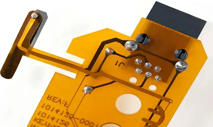
FPC, a type of flexible circuit board, is similar to traditional PCB in its function. FPC soft boards find extensive use in a variety of applications, including FPC antennas, flex PCB connectors, wireless charging coil arrays, and more. The composition of FPC primarily consists of flexible material that features high thermal stability and good electrical insulation properties
Material Composition of an FPC PCB
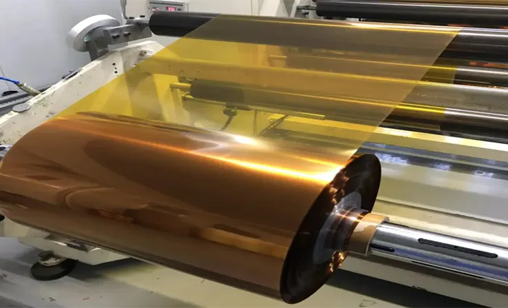
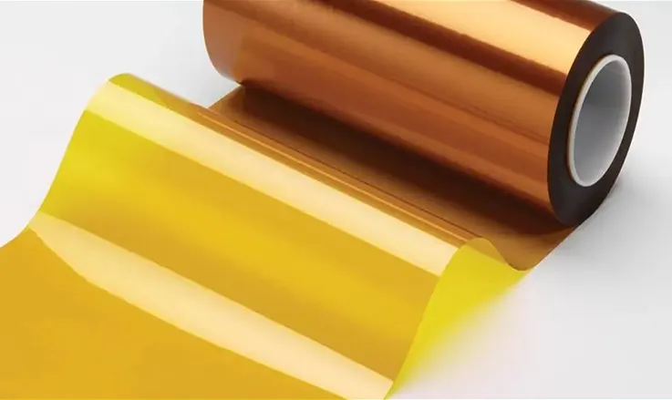
Insulating Substrate: The base substrate material is a crucial component in the manufacturing of both rigid and flexible printed circuit boards. It lays the essential groundwork on which the complete PCB configuration is constructed. For rigid PCB, FR-4 stands as the most widespread substrate material, whereas, for flexible PCB, polyimide (PI) film and PET (polyester) film are the typical materials. Additional polymer films, such as PEN (polyethylene nphthalate), PTFE, and Aramid, are also accessible.
●PI, a thermosetting resin, currently dominates in the fabrication of Flex PCBs. It is esteemed for its superior mechanical attributes, such as robust tensile strength, remarkable thermal stability (-200°C to 300°C), resistance to chemicals, exemplary electrical properties, extraordinary durability, and heat resistance. Additionally, it boasts unique flexibility features, unmatched by other thermosetting resins, even post-thermal polymerization. Nonetheless, PI resin displays a relatively reduced tear strength and moderate absorption of moisture.
●Conversely, PET resin boasts adequate electrical and mechanical properties; however, it is unsuitable for direct soldering as it exhibits poor heat resistance. PEN, another substrate material used in Flex PCB, provides medium-level performance, surpassing PET while not matching the quality of PI in terms of critical mechanical and electrical properties. Throughout the manufacturing process, Flex PCB manufacturers should employ the appropriate substrate material to ensure that the eventual PCB can function seamlessly for its intended application.
Liquid Crystal Polymer (LCP) Substrate: Liquid Crystal Polymer (LCP) substrate is rapidly emerging as a popular substrate material in Flex PCB. LCP is gaining immense popularity due to its ability to mitigate the limitations of Polyimide substrate while retaining all its features. LCP boasts a remarkable moisture or humidity resistance level of 0.04% while exhibiting a dielectric constant of 2.85 at 1GHz, making it ideal for high-speed digital circuits and high-frequency RF circuits.
●LCP substrate’s ability to address the inadequacies of other substrate materials has made it a staple in the Flex PCB manufacturing industry. Furthermore, the melted version of LCP, known as TLCP, can be injection molded and pressed to create a flexible PCB substrate that is readily recyclable.
Given the exceptional performance features attributed to LCP, Flex PCB manufacturers must consider integrating it as their preferred substrate material to manufacture high-performance Flex PCB to fulfill the demands of modern industries.
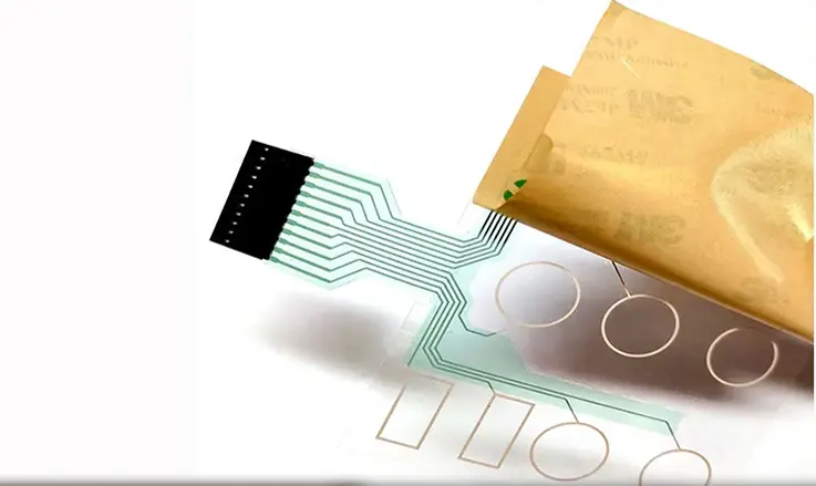
Adhesive: The adhesive sheet functions to adhere the film to the metal foil or to the film when dealing with the cover film. Various adhesive sheets can be utilized for diverse film substrates. For example, adhesive sheets devised for polyester substrates distinct from those employed for polyimide substrates, with the latter bifurcated into epoxy or acrylic types. The bonding sheet is generally selected based on its fluidity and coefficient of thermal expansion. Furthermore, copper-clad polyimide laminates that don’t require adhesive sheets call for lesser upkeep, boast superior chemical resistance, and showcase excellent electrical properties.
●The use of acrylic adhesive sheets poses a challenge as their low glass transition temperature leads to significant contamination during the drilling process, which is difficult to eliminate, thereby negatively impacting the quality of metallized holes. Subsequently, other adhesive materials are deemed inadequate for interlayer bonding sheets of multilayer flexible circuits. Hence, polyimide materials are commonly employed, which exhibit a consistent coefficient of thermal expansion (CTE) when paired with polyimide substrates, eliminating the issue of dimensional instability in multilayer flexible circuits. Furthermore, polyimide adhesive sheets possess exceptional mechanical and electrical properties.
Therefore, Flex PCB manufacturers must choose the right adhesive sheet for a given substrate type to ensure that the resulting PCB possesses the necessary mechanical, electrical, and dimensional stability to function correctly in its intended application.
PI Cover Layer: The use of traditional PI/adhesive coverlay has not always sufficed in satisfying the needs of modern flexible PCB in terms of high density, dimensional stability, and environmental protection. Consequently, a more suitable alternative known as photo-imageable coverlay (PIC) with high flexibility resistance and comparable attributes to solder mask oil has been developed.
●Thus far, liquid or film-type PIC based on modified epoxy or acrylic resin has been extensively studied and applied due to its excellent binding force, high resolution, and flexibility. However, the limited dimensional stability of PIC based on modified epoxy or acrylic resin when used in high-density PCBs and its inferior Tg and heat resistance are notable shortcomings.
Flex PCB manufacturers must consider the factors affecting their desired outcome to choose the most appropriate coverlay material for the intended application. Consequently, the selection of coverlay materials should be conducted carefully with a focus on achieving the desired flexibility, environmental protection, and dimensional stability for the final product.
Flex PCB Stiffener: Stiffeners for flexible circuit boards are commonly categorized as follows: PI stiffener, FR4 stiffener, Steel stiffener, FED stiffener and others. The thickness of PI stiffeners may vary and is denoted by two values following “PI”, which indicate the thickness of PI and adhesive, respectively, both measured in Mil. These values can be adjusted according to the specific requirements of the customer. For instance, PI stiffeners may come in thicknesses ranging from PI1/2 1/2 to PI11, PI21, PI31, and up to PI91 depending on the customer’s needs.
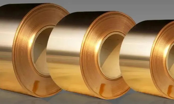
Copper Foil: Acting as a conductive layer, copper foil is meticulously adhered to an insulating base prior to the precision etching of conductive paths. The primary classes of copper foils in use are rolled and electrolytic copper foils. Showcasing superior malleability and resistance to bending, rolled copper foil offers elongation rates spanning 20% to 45%. In contrast, electrolytic copper foil provides an elongation range of 4% to 40%. A 35um (10z) thickness is standard for copper foils, though thinner variants like 18um (0.50z), and thicker renditions, such as 70um (2oz) or even 105um (30z), are also available.
●Electrolytic copper foil is formed via electroplating. The copper particle’s crystal state is such that it has a vertical needle-like shape, which makes it easier to produce vertical line edges during etching, which is advantageous in the manufacture of precision circuits. However, when the bending radius is less than 5m or when dynamic deflections are frequent, the use of needle-shaped copper particles is unsuitable. Rolled copper foil is usually used for flexible circuit substrates due to its malleable structure, featuring copper particles with horizontal shaft-like shapes that can accommodate numerous windings.
Therefore, Flex PCB manufacturers must carefully select the appropriate copper foil type considering several factors, such as flexibility and durability, among other aspects, to ensure the resulting design meets the specific application’s needs.
The Characteristics of Different Copper Foil Types Differ
The use of either rolled copper foil or electrolytic copper foil in Flex PCB manufacturing depends on several factors, including the desired properties of the final product. Although these two types of copper foils are produced using different methods, determining the superior choice can prove challenging.
When choosing the right type of copper foil, Flex PCB manufacturers must consider various design requirements, including flexibility, durability, and precision. Rolled copper foil’s superior ductility and bend resistance, coupled with its horizontal shaft-like copper particle shape, make it particularly suitable for flexible circuit substrates that accommodate numerous windings. In contrast, electrolytic copper foil features a crystal structure consisting of vertical needle-shaped copper particles, which makes it ideal for manufacturing precision circuits requiring vertical line edges during etching.
Ultimately, the selection of copper foil type is dependent on the specific application’s requirements, as the qualities of each type of copper foil offer distinct advantages in particular circumstances. Therefore, Flex PCB manufacturers must conduct careful assessments to determine the most suitable copper foil type and ensure that it meets the demands of the intended application, resulting in a successful end-product.
Two Types of Copper Foil
In some cases, Copper Sheet or Cu Copper may be referred to as a flexible circuit board material by older designers. However, it is worth noting that these terms represent distinct types of copper foil used in Flex PCB manufacturing.
Rolled Annealed Copper Foil or RA Copper Foil represents one classification of copper foil utilized in the fabrication of Flex PCB. Another frequently adopted variant in this context is Electrodeposited Copper, alternatively known as ED Copper Foil.
● ED Vs RA Copper Foil Cost: In regards to the cost of flexible circuit boards, we have found that the average cost of manufacturing using ED Copper Foil is lower than that of RA Copper Foil. However, if there are differing opinions, we welcome input and invite interested parties to reach out to JarnisTech directly.
● ED Vs RA Copper Foil performance: ED Copper Foil is comparatively fragile when compared to RA Copper Foil, and therefore more prone to breakage during the manufacturing process. In contrast, RA Copper Foil offers greater flexibility, making it the preferred choice for FPC copper foil.
When selecting the appropriate copper foil type for Flex PCB production, it is essential to consider several factors, such as durability, flexibility, and precision requirements, among other considerations. Consequently, Flex PCB producers must instigate thorough assessment procedures to pinpoint the optimal copper foil kind geared towards the target application. This meticulous selection process will pave the way for attaining the hoped-for specifications in the finalized Flex PCB product.
One-Stop FPC Circuit Board Manufacturer – JarnisTech
JarnisTech functions as a full-spectrum facilitator of manufacturing services for flexible PCB, encompassing facets from assembly and design to component procurement and product completion. With its foundation laid in 2002, JarnisTech’s functionality extends across two avant-garde PCB production facilities located in Jiangsu and Jiangxi, in addition to an fast PCB assembly factory based in Shenzhen.
We offer a broad range of flexible PCB, including yellow polyimide PCB with 1-12 layers, clear PCB with 1-10 layers, single/double-sided flexible PCB, flexible aluminum PCB, aluminum LED PCB, and HDI flexible PCB.
Here are some of the benefits of having JarnisTech produce your flexible PCB:
● JarnisTech provides turnkey manufacturing services for flexible printed circuit boards (FPC). Our services include FPC design, manufacture, PCB assembly, testing, and box-build assembly.
● We ensure high-quality flexible PCB production that meets strict industry standards such as ISO 9001, IATF 16949, UL, RoHS, and REACH.
● Our customers can benefit from our free and professional one-on-one engineering/design assistance for flexible PCB.
● For high volume flexible PCB/PCBA orders, we offer complete samples and PCBA functional testing to ensure the highest standards of quality.
● We stand behind our manufacturing services and provide quality money-back/free-rework assurance and traceable flexible PCB/PCBA fabrication.
FPC Design Guidelines and Considerations
Here are some possible FPC design guidelines and considerations:
● Bend Radius: The design approach for FPC necessitates cognizance of the bend radius to avert complications that could lead to material crack or fracture. Conventionally, the established minimum bend radius should ideally be proportionate to the FPC thickness, typically constituting a multiple of the same.
● Trace Width and Spacing: The trace width and spacing are critical factors to consider as they affect the electrical performance and can impact manufacturability. They are typically determined by the specific application requirements and should meet the manufacturer’s specifications.
● Material Selection: Flexible Printed Circuits (FPC) can be crafted from a variety of materials each possessing characteristics like thermal conductivity, flexibility and dielectric strength. Material selection should be based on the specific application requirements.
● Connection Points and Pads: The design of connection points and pads should align with the respective components and connectors slated for usage. The dimension and configuration of these zones should be crafted to facilitate robust and dependable connectivity.
● Solder Mask and Silk Screen: The solder mask and silk screen layers should be designed to ensure that they cover the appropriate areas of the FPC and do not interfere with the electrical performance or manufacturability.
● EMI Shielding: FPC can be susceptible to electromagnetic interference (EMI). Adding EMI shielding to the design can be important to minimize the impact of EMI on the electrical performance.
● Thermal Management: FPC can generate heat, which can impact electrical performance and reliability. Thermal management should be designed into the FPC to avoid overheating and damage to the components.
● Testing and Validation: It is important to test and validate the FPC design to ensure it meets the application requirements and is manufacturable. Testing can include electrical performance, mechanical stress testing, and environmental testing.
The Distinction Between PET and FPC
● Polyethylene Terephthalate (PET), a common polymer, is frequently utilized in the production of Flexible Printed Circuit Boards. With its significant transparency and restricted thermal expansion, PET establishes itself as an optimal selection for both solar modules and display panels. Conversely, FPC are immensely flexible entities, appropriate for an array of applications inclusive of high-functioning display panels and indoor uses.
● Flexible Printed Circuit Boards serve as an cost-effective solution that conserves crucial transportation space. The size of traditional rigid PCB can become unwieldy when populated with numerous components. In contrast, FPC are easy to fabricate and assemble, thanks to their flexible design.
● FPC are hybrids of integrated circuits(IC) and thin-film, printed circuit traces. Used in creating flexible circuit boards and electronic devices, FPC incorporate IC chips into thin, flexible plastic sheets. These circuits can be utilized in various applications,like solar panels, electric cars and aircraft, as well as emerging technologies such as aerial drones and wearable electronics.
● Applications of FPC continue to expand, and high-speed electrical circuits demand consistent electrical characteristics. As a result, FPC are relied upon for their ability to maintain signal integrity for a variety of applications, including cutting-edge technologies like aerial drones.
Flexible Printed Circuit Board (FPC) Applications
Flexible printed circuit boards have broad applications across various electrical and electronic sectors. Despite FPC offering versatility and adaptability, their cost is relatively higher than rigid PCB. Nonetheless, FPC have found widespread use in various industries, including:
●Automotive electronics
●Aerospace Components
●Electronics for computers
●Mobile Telephones
●Medical equipment
In addition to the industries mentioned above, flexible PCB are also used in wearable devices, digital cameras, and other applications. The notable benefits of these FPC encompass their flexibility, superior functionality, and multipurpose nature, rendering them perfectly suited for incorporation in sophisticated devices.
Advantages of FPC Board
The technology surrounding Flexible Printed Circuit Boards (FPC) presents numerous benefits making it a desirable choice across various applications. These are the distinct advantages offered by FPC technology:
●More flexibility
●Saves space
●High reliable
●Improved capabilities
●Cost effective
In summary, FPC technology offers greater flexibility, space-saving, higher reliability, enhanced capabilities, and cost savings, making them highly desirable for various complex electronic device applications.
Comparison of FPC With Other Types of Circuit Boards
● Flexibility: Unlike rigid circuit boards, FPC are flexible, thus allowing them to adapt seamlessly into exclusive and curved designs.
● Size and Weight: Typically, FPC are lighter, more compact, and slimmer than alternative circuit board categorizations, which can be beneficial in applications where space is limited.
● Durability: FPC demonstrate heightened durability in comparison with standard circuit boards due to their reduced susceptibility to vibration or flexing damage.
● Intricacy: FPC has the ability to convey numerous electrical signals, fostering the creation of sophisticated designs, thereby driving the development of advanced devices.
● Manufacturing expense: Due to the unique process and equipment required, the production cost associated with FPC can often surpass that of alternative circuit board types. However, this cost pattern has showcased a downward shift over time.
● Fabrication Procedure: When juxtaposed with traditional circuit boards, the assembly of an FPC unmistakably demands a more specialized technique and knowledge base.
● High-Temperature Tolerance: Compared to conventional circuit boards, FPC can withstand elevated temperatures, making them an ideal candidate for implementation in high-temperature sectors such as automotive and industrial domains.
In the end, the selection of circuit board kind is contingent on the particular application needs and design limitations.
Future Prospects of FPC Technology
Anticipated future trajectories for FPC technology encompass the ensuing:
● Downsizing: The trend towards increasingly smaller and thinner FPC will persist, facilitating their incorporation into increasingly compact equipment.
● Integration: The assimilation of FPC with other technologies like sensors, RFID, and LEDs is set to escalate, resulting in the origination of more advanced and smart devices.
● Durability: Enhancements in FPC’s durability are scheduled to persist, shaping them into more suitable components for severe conditions and prolonged usage.
● Economical Efficiency: The formulation of cost-efficient production techniques will reduce the overall expenditure associated with FPC, broadening their accessibility for numerous applications.
● Broadened Usage: The application of FPC technology is set to extend across various realms, encompassing areas such as the medical field, wearable devices, and automotive industry, consequently contributing to a surge in the overall FPC market scope.
Conclusion
Flexible Printed Circuit is a versatile electronic element brimming with a multitude of functionalities. Its broad adaptability marks it as an ideal option for numerous applications seeking a resilient and cost-effective built-in component. Its flexibility and robust capabilities unfold a host of possibilities for engineers to integrate it into their electronic schematics. FPC circuits serve as an exceptional choice for a wide-variety of devices, including mobile phones and solar cells, attributed to its elevated operational efficiency and dependability.
Related Posts:
1. Oshpark PCBs for Optimal Solutions
2. Battery FPC: Advantages, Limitations, Application and Future Developments
3. Flex PCB
4. What Is the Main Differences Between FFC and FPC?
5. Understanding Kapton PCB: Advantages, Challenges, and Applications