
Flexible aluminum PCBs offer a compelling blend of mechanical adaptability and thermal efficiency, making them a preferred choice for advanced electronics in automotive systems, vibrant LED lighting, and sleek consumer devices. These boards thoughtfully integrate materials like polyimide films, thermally conductive dielectrics, and a sturdy aluminum base to achieve a harmonious balance between effective heat dissipation and structural versatility.
This guide explores flexible aluminum PCB technology in depth. It covers material choices, stack-up design, precision processes such as laser cutting, available surface finishes, SMT compatibility, and assembly methods. You’ll also find a comparison of these PCBs with FR4, ceramic, and other metal-core alternatives in terms of cost efficiency and environmental durability. From engineering flexible solutions for wearables and IoT to implementing reliable high-power lighting designs, this resource offers practical insights into manufacturing techniques, supplier evaluation, and strategies for long-term product reliability.
Flexible Aluminum PCBs: An Overview
Flexible Aluminum Printed Circuit Boards (PCBs) bring together mechanical pliability and proficient thermal management, developed to answer the call of today’s sophisticated electronic applications. These circuit boards are constructed with an aluminum substrate that sits beneath flexible layers. This design allows the board to bend and conform to various shapes while efficiently drawing heat away—a noticeable step up from many conventional materials. This pairing of adaptability and aluminum’s heat-conducting nature makes them a great fit for designs that need to be compact yet reliably cool.
Definition and Unique Structure
At its heart, a Flexible Aluminum PCB is thoughtfully layered:
●A thin, lightweight aluminum base acts as an effective heat spreader, channeling thermal energy away from heat-generating components.
●Above this base, a dielectric layer provides electrical insulation for the circuit while also helping transfer heat towards the aluminum.
●Copper foil creates the conductive pathways for electrical signals and power distribution.
This layered construction yields a board that not only fits into complex or tight installation spaces due to its ability to bend but also handles thermal loads more effectively than standard flexible PCBs or rigid FR4 boards.
Table: Typical Layer Structure of Flexible Aluminum PCBs
| Layer | Material | Function | Approx. Thickness |
| Top Layer | Copper Foil | Conducts electrical signals and power | 18–70 µm |
| Dielectric Layer | Polyimide/Epoxy | Insulation and thermal conduction | 50–150 µm |
| Base Layer | Aluminum | Mechanical support and heat dissipation | 0.5–2.0 mm |
How They Differ from Traditional FR4, FPC, and Rigid-Flex PCBs?
Understanding these distinctions can help in choosing the most suitable PCB technology for your needs:
●FR4 PCBs are widespread due to their affordability and structural integrity. However, they can struggle with heat dissipation, particularly in high-power situations.
●Flexible PCBs (FPCs) provide excellent bendability and can be shaped to fit into snug spaces, but they typically don’t include a metallic core for thermal relief.
●Rigid-Flex PCBs combine both rigid and flexible sections. While versatile, they might not offer uniform thermal management across the entire board surface if that’s a specific design goal.
Flexible Aluminum PCBs step in to address the limitations of these alternatives by offering both:
●Mechanical adaptability to conform to various product designs.
●Enhanced heat transfer capabilities, thanks to the integrated aluminum.
This positions them as a strong candidate for applications where thermal performance is a high priority.
Core Benefits in Modern Electronics
Flexible Aluminum PCBs offer several practical advantages for today’s electronics manufacturers and design engineers:
1. Enhanced Thermal Management: The aluminum base efficiently draws heat away from power-intensive components. This contributes to:
●Extended operational lifespan of the product.
●Increased stability and reliability of the electronic assembly.
2. Design Versatility: The pliable nature of these boards allows designers to:
●Develop innovative and compact device layouts.
●Integrate electronics into unconventional or confined spaces, such as in wearable technology, specialized automotive lighting modules, or other custom applications.
3. Increased Durability: They offer good resilience against mechanical stress and vibrations, which adds to their dependability in dynamic operating conditions.
Collectively, these features open up new avenues for Original Equipment Manufacturers (OEMs) and production teams aiming for an effective blend of operational performance and design freedom. Beyond simply supplying these advanced PCBs, a good partner works with clients throughout the product development lifecycle, offering support from initial design consultation and optimization to full-scale manufacturing and assembly services, all tailored to meet your project’s specific demands.
Flexible Aluminum PCB Materials and Thermal Properties
Getting to know the materials that make up Flexible Aluminum PCBs helps in understanding how these boards achieve their balance of flexibility and effective heat management. Each component—from the polyimide film to the aluminum core and the dielectric layers—contributes to the board’s overall performance, especially when thermal handling and mechanical adaptability are both needed.
Polyimide, Aluminum Core, and Dielectric Material Options
Material selection is fundamental to Flexible Aluminum PCB performance and directly influences their suitability for various applications.
1. Polyimide Film: Frequently used as the flexible substrate, polyimide offers:
●Notable thermal stability, maintaining its properties at elevated temperatures.
●Good mechanical resilience, allowing the PCB to bend and flex reliably.
●The ability to withstand high-temperature processes without compromising flexibility, making it a reliable material in flexible aluminum PCB fabrication.
2. Aluminum Core: This is the primary component for thermal management.
●It acts as an efficient heat spreader.
●It possesses high thermal conductivity, which aids in dissipating heat away from heat-sensitive components, thus contributing to device longevity and reliability.
3. Dielectric Materials: Positioned between the copper traces and the aluminum core, these materials are selected to:
●Provide electrical insulation, preventing shorts between the circuitry and the metal core.
●Facilitate efficient heat transfer from the circuit to the aluminum heat spreader.
The precise choice and combination of these materials can often be tailored. Experienced manufacturers can customize these layers, enabling optimization of the PCB’s performance to meet an application’s specific thermal demands and mechanical requirements.
Table: Common Material Options for Flexible Aluminum PCBs
| Component | Material Type | Key Properties | Typical Thickness |
| Flexible Substrate | Polyimide | High-temp resistance, flexible, stable | 25–125 µm |
| Metal Core | Aluminum 1100 / 5052 | Thermal conductivity: 150–235 W/m·K | 0.5–2.0 mm |
| Dielectric Layer | Epoxy/Polyimide blends | Insulating, thermally conductive | 50–150 µm |
| Conductive Layer | Rolled or Electrolytic Copper | Conducts signals and power | 18–70 µm |
Thermal Conductivity, Insulation, and Heat Resistance
The thermal characteristics of Flexible Aluminum PCBs are shaped by the interplay of their constituent materials.
1. Conductivity: This measures how efficiently heat travels through the PCB materials. It’s a significant consideration when designing for high-power devices or those in compact enclosures.
●Aluminum’s inherent high thermal conductivity is substantially better than that of traditional FR4 substrates. This helps to prevent overheating and can contribute to maintaining signal integrity under load.
2. Electrical Insulation: The dielectric layer is chosen to provide robust electrical insulation without substantially hindering the heat flow path to the aluminum core.
3. Heat Resistance: The complete material stack is engineered for heat resistance, ensuring the PCB can operate reliably during continuous exposure to the elevated temperatures often encountered in applications like:
●LED lighting modules
●Automotive electronics
●Power conversion systems
A carefully engineered balance between effective heat conduction and dependable electrical insulation allows flexible aluminum PCBs to perform consistently, even under demanding thermal conditions.
Table: Comparative Thermal Performance Indicators
| Property | Flexible Aluminum PCB | Traditional FR4 PCB | Flexible PCB (FPC) |
| Thermal Conductivity (Base) | 150–235 W/m·K | 0.3–0.5 W/m·K | ~0.3 W/m·K |
| Dielectric Thermal Transfer | 0.8–2.2 W/m·K (typical) | 0.3–0.5 W/m·K | 0.2–0.4 W/m·K |
| Max Operating Temp | 130–250°C (material-dependent) | ~130–150°C | 150–200°C |
| Insulation Breakdown Voltage | >2.5 kV (depending on stack-up) | ~1.5–2.0 kV | 1.5–2.5 kV |
Surface Finishes: ENIG, OSP, HASL and Their Functions
The surface finish applied to Flexible Aluminum PCBs protects the copper circuitry and also affects solderability and long-term device durability. Common options include:
ENIG (Electroless Nickel Immersion Gold):
●Provides a very flat surface, beneficial for fine-pitch components.
●Offers good oxidation resistance.
●Contributes to reliable solder joints.
OSP (Organic Solderability Preservative):
●A cost-effective and more environmentally considerate option.
●Suited for moderate production volumes.
●Preserves the solderability of the copper pads until the assembly stage.
HASL (Hot Air Solder Leveling):
●While less frequently used on flexible boards, HASL provides a thicker solder coating.
●This can enhance mechanical strength in some specific use cases.
The selection of an appropriate surface finish is guided by your specific assembly processes, the anticipated environmental exposure of the end product, and the device’s electrical characteristics. Our team can help you navigate these considerations to select the optimal finish for your application and manufacturing needs.
Flexible Aluminum PCB Design and Engineering Considerations

Designing flexible aluminum PCBs requires a thoughtful combination of material science and practical engineering to meet the demands of various industries, from consumer electronics to automotive systems. Achieving reliable performance means giving careful attention to mechanical flexibility, thermal behavior, and electrical integrity, all while keeping manufacturability in perspective.
Layer Stack-Up, Bend Radius, and Trace Routing
The physical construction and layout of a flexible aluminum PCB are foundational to its success. Thoughtful planning includes:
1. Layer Stack-Up: This defines the specific arrangement of conductive copper layers, dielectric insulation materials, and the aluminum core. This configuration influences not only electrical performance (like signal integrity and impedance control) but also the board’s flexibility and thermal response characteristics.
2. Bend Radius: Careful planning of the minimum bend radius is needed to prevent damage to the PCB during installation or during dynamic flexing in its application. This radius is typically determined by the total thickness of the board and the properties of the materials used.
3. Trace Routing: Copper traces must be routed to meet signal integrity requirements and avoid stress concentration points, particularly near bend areas, which could otherwise lead to cracking or failure over time.
An experienced engineering team will often collaborate with clients to define an optimal layer stack-up, establish suitable bend radius parameters, and develop trace routing strategies, ensuring the flexible aluminum PCB is designed for both performance and resilience.
Table: Design Considerations for Mechanical Flexibility
| Design Element | Typical Specification | Engineering Guideline |
| Layer Stack-Up | 1–2 copper layers with dielectric + aluminum | Maintain symmetrical structure for flex reliability |
| Minimum Bend Radius | 6× board thickness (static); 10× (dynamic) | e.g., 1.0 mm board → min radius = 6–10 mm |
| Trace Routing Width | ≥0.15 mm (for signals); ≥0.3 mm (for power) | Avoid 90° turns; use 45° or curves for bend regions |
| Trace Spacing | ≥0.15 mm standard | Increase spacing near bends to reduce stress |
Thermal Simulation and Stress Analysis
Predictive engineering techniques play a large part in preempting issues and refining designs before production:
1. Thermal Simulation: Prior to manufacturing, engineers often use specialized software to:
●Visualize how heat will flow across the flexible aluminum PCB under operational loads.
●Identify potential hotspots that could affect component lifespan or board integrity. This insight allows for adjustments in material selection, component placement, or trace design to enhance heat dissipation.
2. Stress Analysis: This complements thermal simulation by:
●Predicting mechanical strains that may arise from bending, vibration, or temperature cycling.
●Allowing designers to reinforce vulnerable areas or specify more robust dielectric materials for improved durability.
Comprehensive design support often includes utilizing such predictive tools to help identify potential issues early, assist in optimizing designs for thermal management and mechanical durability, and ultimately contribute to reducing development time and improving final product reliability.
EMI Shielding and High-Frequency Circuit Design
Managing electromagnetic interference (EMI) and ensuring signal integrity are particular considerations in many modern electronic devices:
1. EMI Challenges: In flexible aluminum PCB design, EMI can be a factor, especially for high-frequency applications such as:
●Wireless communication modules.
●Automotive radar and sensor systems.
2.Mitigation Techniques: To minimize signal disruption and noise coupling, designs often incorporate:
●Proper grounding strategies.
●Dedicated shielding layers or conductive coatings.
●Controlled impedance traces for consistent signal transmission.
3. Role of Aluminum Core: The aluminum core itself can contribute to shielding if integrated thoughtfully into the design. However, depending on the sensitivity of the device and the electromagnetic environment, additional shielding measures may be needed.
Addressing EMI and ensuring signal integrity in high-frequency designs are specialized areas. Developing effective grounding, shielding, and controlled impedance strategies helps ensure flexible aluminum PCBs perform reliably, even in electromagnetically active environments.
Types of Flexible Aluminum PCBs and Custom Configurations
Flexible aluminum PCBs are available in diverse forms to satisfy a broad spectrum of application needs, extending from simple single-layer boards to more intricate multilayer and hybrid constructions. Understanding these configurations assists manufacturers, design engineers, and OEMs in selecting the most suitable option for their specific thermal, mechanical, and electrical requirements.
Single-Layer, Multilayer, and Hybrid Rigid-Flex Options
The fundamental structure of flexible aluminum PCBs can vary significantly to accommodate different levels of complexity and performance:
Single-Layer Flexible Aluminum PCBs:
●These feature a straightforward construction with a single copper circuit layer on a flexible dielectric material, positioned over an aluminum substrate.
●They are frequently selected for applications where a balance between flexibility, heat dissipation, and cost-effectiveness is sought.
Multilayer Flexible Aluminum PCBs:
●These build upon the single-layer design by stacking multiple conductive and dielectric layers.
●This approach allows for increased circuit density and more complex routing, proving advantageous in compact or multifunctional electronic devices.
Hybrid Rigid-Flex Aluminum Designs:
●These constructions integrate sections of flexible aluminum PCB with rigid PCB parts.
●They combine the mechanical robustness of rigid boards with the adaptability of flexible aluminum layers, making them well-suited for devices that demand both structural durability and conformational flexibility.
We have the capability to produce a full range of these configurations, from uncomplicated single-layer boards to sophisticated multilayer and hybrid rigid-flex aluminum PCBs. Our team collaborates with you to determine the most effective construction for your specific application.
Flexible LED Strip PCBs, Automotive PCBs, and Custom Shapes
Certain industries and applications benefit from flexible aluminum PCBs designed for unique forms and operational demands:
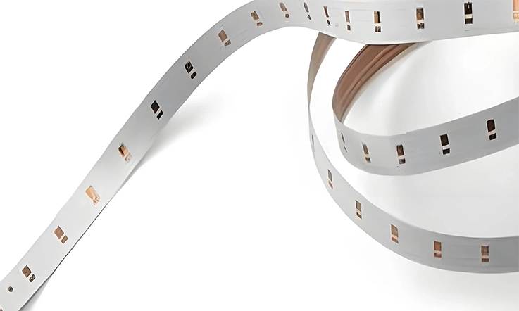
Flexible LED Strip PCBs:
●LED strip lighting often utilizes flexible boards with aluminum cores due to their proficient heat management for high-power LEDs and their ability to conform to diverse installation profiles.
Automotive PCBs:
●Automotive electronics require flexible aluminum PCBs that can withstand operational vibrations and temperature fluctuations while fitting into the often constrained spaces within vehicles.
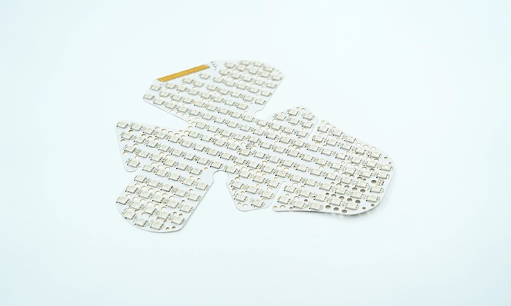
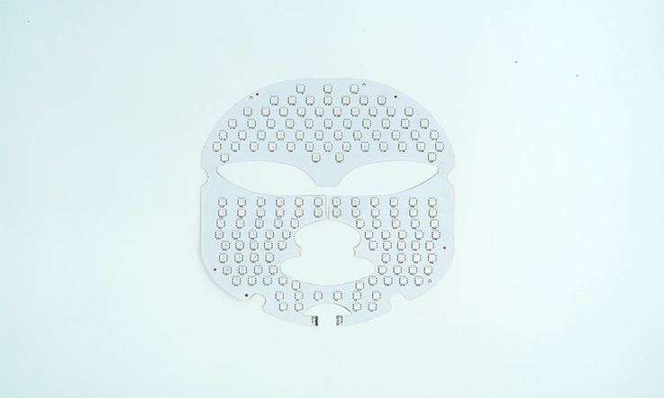
Custom-Shaped Flexible Aluminum PCBs:
●These cater to applications where standard rectangular or square forms are not adequate.
●They allow designers to create layouts that precisely match the contours of a product’s housing, which can lead to improvements in both performance and overall product aesthetics.
Expertise in developing and manufacturing flexible aluminum PCBs for specialized applications means the ability to produce custom shapes tailored for LED lighting, automotive systems, or any product requiring a non-standard form factor, ensuring seamless integration and optimal function.
Table 2: Use Case Matrix for Specialized Flexible Aluminum PCBs
| Application Type | Typical Thickness (mm) | Minimum Bend Radius | Thermal Conductivity (W/m·K) | Common Form Factor |
| LED Strip PCBs | 0.6–1.2 | ≥10× board thickness | 2.0–3.0 | Linear, serpentine |
| Automotive Electronics | 1.0–1.6 | ≥12× board thickness | 2.2–3.5 | Folded, stacked |
| Custom-Shaped Flex PCBs | ≤0.8 | ≥6× board thickness | 1.5–2.5 | Circular, irregular |
Low-Profile, Ultra-Thin, and High-Thermal Variants
To meet specific constraints related to space and thermal management, specialized variants are available:
Low-Profile Boards:
●These designs reduce the overall vertical height of electronic assemblies, a feature of considerable benefit in compact consumer devices and other space-sensitive applications.
Ultra-Thin Flexible Aluminum PCBs:
●Taking thinness a step further, these boards offer remarkable bending capabilities, often without a significant reduction in their thermal conduction properties.
High-Thermal Variants:
●For applications that generate intense heat, these variants may incorporate thicker aluminum cores or specialized dielectric materials with enhanced thermal conductivity.
●This improves heat dissipation, helping to ensure that device performance remains steady even under thermally demanding conditions.
Flexible Aluminum PCB Manufacturing Process and Capabilities
Producing flexible aluminum PCBs involves several precise manufacturing steps that shape the board’s performance and durability. From initial material preparation through to final inspection, each phase requires careful attention to detail to achieve the intended balance between flexibility and effective thermal management.
CNC Drilling, Lamination, and Laser Cutting Techniques
Advanced manufacturing techniques are employed to ensure precision and reliability in every flexible aluminum PCB:
●CNC Drilling: Provides exact holes and vias (vertical interconnect access points) within the PCB structure. This enables dependable electrical connections between different layers while accommodating the board’s need for mechanical flexibility.
●Lamination: This process presses the polyimide film, copper circuitry, dielectric layers, and the aluminum core together under controlled heat and pressure. It results in a unified and robust board structure, ensuring consistent thickness and mechanical integrity.
●Laser Cutting: Adds a high degree of precision in defining complex board outlines, intricate shapes, and internal cutouts. This technique is particularly advantageous for custom configurations or when fitting PCBs into tight or uniquely shaped installation spaces.
Table 1: Core Manufacturing Processes and Their Technical Parameters
| Process | Precision Level | Functionality Summary | Key Benefit |
| CNC Drilling | ±0.05 mm | Creates vias and mounting holes | Ensures accurate interconnections |
| Lamination | Pressure: 2–4 MPa Temp: 180–200°C | Bonds layers (polyimide, copper, dielectric, aluminum) | Maintains structural integrity |
| Laser Cutting | ±0.03 mm | Shapes complex outlines, internal cutouts | Enables custom form factors |
Facilities utilizing these advanced manufacturing technologies, operated by skilled technicians, can produce flexible aluminum PCBs that precisely meet design specifications and are built to perform reliably under conditions of bending and thermal stress.
Quality Control: Adherence to ISO, UL, and RoHS Standards
Maintaining high standards throughout the manufacturing cycle is a mark of a proficient operation. A commitment to quality is demonstrated through:
ISO Certification (e.g., ISO 9001):
●Compliance with relevant ISO standards (such as ISO 9001) ensures that manufacturing processes are consistently monitored, controlled, and improved for quality output and process repeatability.
UL Certification:
●This indicates that flexible aluminum PCBs meet recognized safety and flammability requirements, making them suitable for a wide array of consumer and industrial products.
RoHS Compliance:
●This certification confirms that the materials used in the PCBs adhere to environmental regulations by limiting the use of specified hazardous substances.
Together, these certifications and compliances reflect a dedication to delivering flexible aluminum PCBs that are safe, dependable, and manufactured with environmental responsibility in mind.
Mass Production and Prototyping Services
A comprehensive range of manufacturing services can support your project from its initial stages through to full-scale production:
1. Prototyping Services: Rapid prototyping allows engineers and designers to thoroughly test their flexible aluminum PCB designs. This includes verifying thermal performance, flexibility characteristics, and electrical functionality under real-world conditions before committing to volume manufacturing.
2. Mass Production Capabilities: When designs are finalized and ready for larger volumes, factories leveraging advanced equipment and streamlined workflows ensure consistent quality and efficient output. This approach reliably supports industries such as consumer electronics, automotive, and medical devices, where high volumes and precise specifications are standard.
Table 3: Comparison of Prototyping vs. Mass Production Services
| Service Type | Lead Time (Typical) | Minimum Order Quantity (MOQ) | Customization Level | Use Case |
| Rapid Prototyping | 3–7 working days | 1–10 pieces | Very High | Design verification, functional testing |
| Mass Production | 10–25 working days | 500+ pieces | Medium–High | Full-scale deployment in various sectors |
Flexible Aluminum PCB Assembly Process and SMT Compatibility
Assembling flexible aluminum PCBs involves navigating distinct considerations compared to conventional rigid boards. The integrated metal core influences soldering behavior and component placement, necessitating tailored techniques to preserve both electrical integrity and thermal efficiency throughout the assembly process.
Soldering on Metal Substrates: Considerations and Solutions
Soldering components onto aluminum-based PCBs presents specific thermal challenges that require careful management:
1. The Challenge: The high thermal conductivity of the aluminum substrate can cause heat to dissipate very quickly from the soldering area. If not properly managed, this can affect solder joint formation and lead to inconsistent or weak connections.
2. Addressing these dynamics often involves:
●Specialized Materials: Utilizing solder pastes and fluxes specifically formulated for use with metal substrates to ensure proper wetting and bond strength.
●Optimized Thermal Profiles: Employing precisely controlled reflow oven profiles that are optimized for the thermal characteristics of aluminum, ensuring consistent solder quality.
●Design for Assembly (DFA) Collaboration: Working with design teams to advise on incorporating elements like thermal relief patterns and strategic pad layouts can significantly improve solderability by managing heat flow at the joint level.
SMT/SMD Component Placement Techniques
Surface Mount Technology (SMT) assembly on flexible aluminum PCBs requires precision and specialized handling:
●The Challenge: The inherent flexibility of these boards can sometimes lead to warping or minor shifting during automated pick-and-place operations if the board is not adequately supported.
Techniques for Precision often include:
●Stabilization Methods: Employing custom-designed fixtures or carriers that securely hold the flexible aluminum PCB during the SMT process, ensuring stability and accurate component placement.
●Component Compatibility: Emphasizing the selection of SMT/SMD components with compatibility in mind, considering factors such as their heat tolerance during reflow and their ability to withstand any mechanical stress associated with flexible circuits.
Thermal Management in PCB Assembly
Managing heat effectively is a consistent theme, both during the assembly process and in the final application of the assembled board:
●During Assembly: While the aluminum core is designed to be an excellent heat sink in operation, the assembly process itself must avoid excessive heat that could potentially damage sensitive components or compromise the board’s integrity. This involves the use of carefully controlled soldering temperatures and defined cooling rates as part of standard manufacturing protocols.
●Post-Assembly Performance: The inherent design of a flexible aluminum PCB facilitates efficient heat transfer away from heat-sensitive components during device operation. This supports dependable performance, particularly in high-power environments or compact enclosures where thermal buildup can be a concern.
Table 3: Thermal Control Measures in Assembly and Operation
| Phase | Thermal Consideration | Implementation Strategy |
| Assembly (Reflow Phase) | Avoid hot spots and warping | Profile tuning + thermal shielding if necessary |
| Cooling (Post-Soldering) | Prevent stress fractures in components | Gradual cooling curve (2–4°C/s) |
| In-Use Thermal Handling | Efficient heat dissipation from active components | Thicker aluminum core or high-k dielectric usage |
| Application Scenarios | LED arrays, automotive modules, power supplies | Prioritize thermal conductivity in stack-up |
Applications in Automotive, LED, and Consumer Electronics
Flexible aluminum PCBs have become a frequent selection across various industries due to their proficient combination of heat dissipation with adaptability. Their distinct structure is well-suited to environments where space is limited but performance expectations are high, such as in automotive electronics, LED lighting systems, and diverse consumer devices.
Automotive LED Control Modules and Sensors
In the automotive sector, flexible aluminum PCBs are regularly utilized for critical components, offering several advantages:
●Foundation for Control Systems: They often serve as the substrate for LED control modules and various sensor circuits that are integral to modern vehicle functions.
●Environmental Resilience: These PCBs are designed to handle the temperature fluctuations and mechanical vibrations commonly found in demanding vehicle environments.
●Heat Management: The aluminum base effectively distributes heat away from LED arrays and other sensitive electronic components, contributing to consistent performance and extended operational life.
●Design Accommodations: They support complex wiring configurations within compact spaces, aiding in the design of streamlined and reliable automotive systems.
High-Power LED Lighting and Heat-Sensitive Devices
High-power LED lighting systems and other devices sensitive to thermal conditions particularly benefit from the characteristics of flexible aluminum PCBs:
●Efficient Thermal Pathway: The construction provides an effective pathway for heat generated by high-power LEDs to be drawn away from the LED chips. Managing heat in such devices is a primary consideration for maintaining brightness and achieving long operational lifespans.
●Prevention of Thermal Degradation: By managing heat, these PCBs help prevent thermal degradation and performance loss in LEDs over time.
●Stable Operation for Sensitive Devices: Other heat-sensitive electronic components integrated onto these boards rely on the combined thermal properties to operate reliably without overheating.
●Consistent Lighting Performance: These attributes allow designers to create robust lighting solutions that perform steadily and dependably over extended periods.
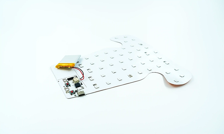
Wearables, IoT, and Smart Home Integration
The unique properties of flexible aluminum PCBs make them highly suitable for the rapidly growing markets of wearable technology, Internet of Things (IoT) devices, and smart home applications:
●Form Factor Advantages: Their flexibility, lightweight nature, and thin profiles allow complex circuitry to be integrated into small, ergonomic, or irregularly shaped housings typical of these devices.
●Thermal Regulation: The aluminum layer provides necessary heat management, which is beneficial for devices intended for continuous operation or those worn close to the body.
●Reliable Connectivity: For IoT and smart home systems, dependable performance with minimal thermal concerns helps ensure that devices respond accurately and consistently to user commands and environmental inputs.
●Adaptability for Innovation: This overall adaptability makes flexible aluminum PCBs a preferred substrate for developing compact, connected technology.
Manufacturing flexible aluminum PCBs with the tight tolerances and specific profiles needed for wearables, IoT, and smart home devices supports the development of innovative products that successfully combine compact designs with effective thermal control.
Cost Factors and ROI in Flexible Aluminum PCB Projects
When considering an investment in flexible aluminum PCBs, it’s beneficial to examine how material and design choices affect both initial expenditures and long-term returns. Understanding these dynamics helps manufacturers, design engineers, and OEMs make informed decisions that align with product performance objectives and budgetary considerations.
Material vs. Performance Considerations
The selection of materials for flexible aluminum PCBs has a direct bearing on both cost and ultimate performance. Aspects to consider include:
●Influence of Material Choices: The specific aluminum alloys, dielectric layers (such as polyimide), and surface finishes (e.g., ENIG, OSP, HASL) selected will directly influence the board’s thermal conductivity, mechanical flexibility, and electrical reliability.
●Investment in Higher-Grade Materials: Choosing materials with enhanced properties might increase initial manufacturing expenses. However, this can often result in superior heat dissipation, increased durability, and longer-lasting assemblies, potentially lowering total lifecycle costs.
●Balancing Performance and Cost: Conversely, optimizing material usage without compromising designated functional properties can achieve a practical balance that meets both performance demands and cost targets.
Lifecycle and Environmental Durability
The expected operational lifespan and resilience of a flexible aluminum PCB are significant factors in its overall value:
●Environmental Endurance: A board’s ability to withstand varying environmental conditions—including humidity, temperature cycles, and mechanical stress—directly affects its effective lifecycle and reliability.
●Assessing Durability: Considerations for durability include the aluminum core’s resistance to corrosion and the dielectric material’s capacity to maintain its insulating properties consistently over time and across different conditions.
●Designing for Longevity: For products intended for markets such as automotive or consumer electronics, where sustained reliability over extended periods is a common expectation, design choices that promote longevity and reduce the likelihood of premature failure are particularly advantageous.
Table 2: Durability Metrics and Lifecycle Considerations
| Parameter | Standard Value/Range | Relevance to ROI |
| Operating Temp. Range | –40°C to +125°C | Ensures performance in automotive/industrial |
| Flex Life (Cycles to Failure) | ≥10,000 bends (at defined radius) | Indicates mechanical endurance |
| Moisture Resistance | ≤0.1% absorption (polyimide) | Reduces corrosion, improves reliability |
| Corrosion Resistance (Al Core) | Anodized or coated for protection | Extends life in humid/salty environments |
Cost Comparison with Other Substrate Technologies
Evaluating flexible aluminum PCBs against other common substrate options reveals distinct cost-performance profiles:
●FR4 Boards: These often present lower initial production costs. However, their limited thermal management capabilities can sometimes lead to increased total system expenses if supplementary cooling solutions (like heat sinks or fans) become necessary.
●Ceramic PCBs: While offering excellent heat dissipation, ceramic substrates typically come with higher material and processing costs and provide less mechanical flexibility compared to other options.
●Flexible Aluminum PCBs: These generally offer a compelling middle ground. They deliver effective thermal handling and mechanical adaptability at a cost point that is favorable for a wide array of high-performance electronics applications, often providing a better overall value when thermal management is a requirement.
How to Choose the Right Flexible Aluminum PCB Manufacturer?
Selecting a suitable manufacturer for your flexible aluminum PCBs involves considerations that go beyond initial price quotations. It’s about identifying a partner who deeply understands the specific nuances of flexible aluminum PCB fabrication, intricate design considerations, and potential assembly challenges. The right manufacturing partner should be capable of providing tailored solutions that align precisely with your project’s technical specifications and production volumes, while consistently upholding quality standards demonstrated by industry certifications like ISO, UL, and RoHS.
Evaluating Experience, Customization, and Engineering Support
When assessing potential manufacturers, consider these attributes:
●Proven Experience: Look for demonstrated expertise with the specific materials used in flexible aluminum PCBs, a history of successfully producing diverse layer stack-up designs, and a strong understanding of effective thermal management techniques. This kind of experience can tangibly improve your product’s performance and reliability.
●Engineering and Design Support: A valuable partner will offer engineering support to help optimize your PCB design. This might involve collaboration on improving thermal conductivity through dielectric material choices, refining trace routing for better signal integrity, or advising on design for manufacturability (DFM) to prevent issues later on.
●Customization Capabilities: Assess their ability to produce tailored solutions beyond standard offerings. This could include specialized configurations for flexible LED strip PCBs, complex hybrid rigid-flex aluminum designs, or other custom shapes and constructions, reflecting their adaptability to diverse project needs.
●Collaborative Approach: A manufacturer who engages in hands-on technical collaboration throughout the design and manufacturing process often contributes to more dependable products and streamlined assembly operations.
Comparing Local vs. Overseas Manufacturing Partners
The decision between sourcing locally or from overseas involves weighing several operational and financial factors:
1.Local Manufacturing Partners:
●Potential Advantages: May offer quicker turnaround times, more straightforward communication, and easier access to in-person technical support or site visits. This can be particularly beneficial during rapid prototype development or for time-sensitive orders.
●Points to Consider: Unit costs may sometimes be higher compared to some overseas alternatives, depending on the region and order volume.
2.Overseas Manufacturing Partners:
●Potential Advantages: Often provide competitive pricing, especially for high-volume production runs, and can offer significant scalability.
●Points to Consider: May entail longer lead times due to shipping, potential communication challenges across different time zones and languages, and require robust processes for remote quality assurance and logistical coordination.
3.Universal Evaluation Criteria: Regardless of the manufacturer’s location, thoroughly evaluate:
●Their relevant industry certifications (e.g., ISO for quality management, UL for safety, RoHS for material compliance).
●Their specific manufacturing capabilities, including the precision of their CNC drilling, lamination processes, and laser cutting techniques.
●Their verifiable track record in consistently delivering flexible aluminum PCBs that meet stringent design specifications and thermal performance criteria.
Table 2: Local vs. Overseas Manufacturer Comparison
| Factor | Local Partner | Overseas Partner |
| Lead Time | Shorter (1–3 weeks for prototypes) | Longer (3–6 weeks including shipping) |
| Cost Per Unit (High-Volume) | Higher | Lower |
| Communication & Collaboration | Direct, real-time | May involve time zone/language barriers |
| IP Protection | Stronger legal recourse | Varies based on region |
| Onsite Visits/Inspections | Easy to arrange | Often not feasible |
| Scalability | Moderate | High |
Checklist: Key Questions for Your Potential Supplier
To ensure you select a partner well-equipped for your project, consider asking potential suppliers about the following:
1.Materials and Design Expertise:
●What range of flexible aluminum PCB materials (specific aluminum alloys, polyimide types, dielectric options) do you specialize in or recommend for an application like mine?
●Do you offer Design for Manufacturability (DFM) or Design for Assembly (DFA) reviews for flexible aluminum PCB projects?
●How can you assist in optimizing layer stack-ups, trace routing for signal integrity, or features for enhanced thermal management?
2.Manufacturing & Customization Capabilities:
●Could you detail your capabilities and precision levels for CNC drilling, lamination, and laser cutting, especially for flexible and custom-shaped boards?
●What is your experience in producing specialized configurations, such as low-profile, ultra-thin boards, or complex 3D shapes?
●Which surface finishes (e.g., ENIG, OSP, HASL) do you provide, and what are your recommendations for flexible aluminum applications?
3.Assembly Services (If offered and required):
●What is your experience with SMT/SMD component assembly specifically onto flexible aluminum substrates?
●How do your processes address challenges like soldering effectively on metal substrates and ensuring board stability during component placement?
4.Quality Assurance and Reliability:
●What are your standard quality control procedures and in-process inspections for flexible aluminum PCBs?
●What testing capabilities do you have for verifying aspects like thermal conductivity, electrical integrity, and environmental durability?
●Can you provide documentation for your ISO, UL, and RoHS certifications?
5.Business Practices & Support:
●What are your typical lead times for both prototyping and mass production phases?
●How is communication managed, and what technical support is available throughout the project lifecycle?
●How do you ensure the protection of our intellectual property (IP) throughout the design and manufacturing process?
FAQ & Flexible Aluminum PCB
1.What are the typical thickness ranges for the aluminum core in flexible aluminum PCBs?
Aluminum core thickness typically ranges from 0.4mm to 3.2mm, tailored to specific thermal and mechanical requirements.
2.Can flexible aluminum PCBs withstand repeated flexing (dynamic flexing), and what is their typical fatigue life?
Primarily designed for “flex-to-install.” Limited dynamic flexing is possible with careful design; fatigue life is application-specific and generally lower than standard FPCs without a metal core.
3.Are there standard panel sizes for manufacturing flexible aluminum PCBs?
Yes, manufacturers generally work with standard industry panel sizes (e.g., 18×24 inches, 12×18 inches) to optimize material utilization and cost-effectiveness.
4.What is the typical minimum trace width and spacing achievable on flexible aluminum PCBs?
Typically around 3-5 mils (0.075-0.127mm), varying by manufacturer capability and design complexity, similar to standard flexible circuits.
5.What kind of tooling investment is generally required for custom-shaped flexible aluminum PCBs?
Laser cutting often minimizes tooling costs for prototypes or low volumes. High-volume production might use punching dies, which involve higher initial Non-Recurring Engineering (NRE) costs.
6.Are there specific solder mask color or type options available for flexible aluminum PCBs?
Yes, flexible solder masks are used. Common colors include green, white, and black, with options depending on material compatibility, flexibility, and thermal requirements.


