
In the realm of printed circuit boards (PCBs), a protective coating layer called a solder mask is used for rigid PCBs, while coverlay is the term used for flexible PCBs. The purpose of solder mask and coverlay on their respective PCBs is the same: to protect and insulate the circuitry. However, a flex coverlay contributes essential flexibility and durability to the design of a flexible PCB.
In the manufacturing process of flexible PCBs, the external circuitry is encapsulated and safeguarded with a flex circuit coverlay, alternatively referred to as a coverfilm. This article aims to provide a comprehensive introduction to the coverlay of flexible PCBs, encompassing its materials, colors, and thicknesses, as well as addressing common queries regarding flexible PCB coverlay.
What Is Coverlay in FPC PCBs ?
The FPC Coverlay is an integral part of flexible printed circuit boards that serves to protect and encapsulate the external copper circuit layers. This layer is created using a solid polyimide sheet that is coated with a layer of flexible adhesive, and it serves the same purpose as a solder mask used in rigid boards.
Since traditional solder masks do not offer sufficient flexibility required by flex circuits, coverlay is bonded to these circuits in order to provide higher bendability. Coverlay is exclusively used for flexible printed circuit boards.
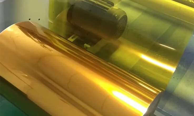
In contrast to rigid PCB solder mask, coverlay comes in roll form, although it may also be supplied as a sheet that can be trimmed down to the required size. In order to create the coverlay apertures, various methods are used, such as drilling, routing, punching, or laser cutting, depending upon the complexity of the flex PCB design and size of the features.
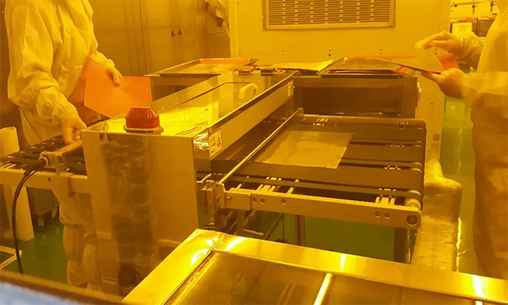
Once the necessary pattern has been formed, the coverlay film is aligned to the copper circuit layer and pressed under heat and pressure for an extended period of time to cure the adhesive and finish bonding the coverlay to the flexible circuit board.
The most commonly utilized approach for generating feature openings in coverlay is through drilling. Nonetheless, when designing coverlay, there are various factors to consider:
● During the drilling process of coverlay, mechanical NC drills utilize round bits, resulting in cylindrical or oval-shaped holes in the coverlay film. These holes often cover square surface mount pads.
● Since there may be production tolerances involved with drilling, the FPC manufacturer will need to consider using a larger annular ring to handle any adhesive squeeze out that occurs during the pressing operation.
● To prevent delamination and ensure strong adhesive bonding, the minimum web thickness must be adequate.
In some instances, JarnisTech may employ TPI (thermoplastic PI) instead of coverlay in multilayer flexible printed circuits to enhance the electrical isolation between the inner copper layers.
Properties and Benefits of FPC Coverlay
Here are some properties and benefits of FPC Coverlay:
● Flexible: The Coverlay is flexible and conformable to the FPC’s substrate, which allows it to bend and flex with the FPC during operation.
● Electrical Insulation: The Coverlay provides electrical insulation for the metal traces on the FPC’s substrate, which prevents short circuits and signal interference.
● Chemical Resistance: The Coverlay is resistant to chemicals, corrosion, and humidity, which protects the FPC from environmental damage.
● Thermal Stability: The Coverlay has good thermal stability and can withstand high-temperature operation without delaminating or cracking.
● Mechanical Strength: The Coverlay provides mechanical strength and support for the FPC, which enables it to withstand mechanical stress, such as bending, twisting, and vibration.
● Adhesion: The Coverlay has good adhesion to the FPC’s substrate, which ensures proper bonding and prevents delamination.
● Customizability: The Coverlay can be customized to the FPC’s design requirements, such as thickness, dielectric properties, and surface finish.
● Miniaturization: The Coverlay is thin and lightweight, which enables the miniaturization of electronic products and reduces their weight and size.
● Cost-effective: The Coverlay is a cost-effective solution for protecting and insulating FPCs compared to other conformal coatings or encapsulation methods.
● Design Flexibility: FPC Coverlay provides design flexibility for the FPCs by enabling the routing, shielding, and protection of the circuitry in almost any shape or form.
Structure of the Flexible printed circuit (FPC) Coverlay
The flex PCB coverlay is composed of three layers: protective insulation (PI), adhesive layer (AD), and release paper (RELEASE). However, it is worth noting that the role of the release paper is purely protective, and it is removed before use. The coverlay is primarily constructed using PI and AD, with the release paper serving as a temporary layer that is peeled away once the protective function is fulfilled.
●Polyimide short Name: PI.
●Epoxy Adhesives short Name: AD.
●Flex PCB coverlay colors: yellow, white, black.
●The use thickness of PI can be either 12.5um or 25um, special cases can be customized.
●AD usage thickness can be either 15um or 25um, and exceptional circumstances may be tailored to the user’s specific requirements.
Common Coverlay Configurations
| Coverlay Consists of Adhesive and Polyimide (PI) | ||
| Name | Polyimide Thickness μm (mil) | Adhesive Thickness μm (mil) |
| 12.5/15 | 12.5 (0.5) | 15 (0.6) |
| 12.5/25 | 12.5 (0.5) | 25 (1.0) |
| 25/25 | 25 (1.0) | 25 (1.0) |
| 25/35 | 25 (1.0) | 35 (1.4) |
| 25/50 | 25 (1.0) | 50 (1.0) |
The flex PCB coverlay size parameters that are most frequently used in the market include PI 12.5um/15um AD and PI 25um/25um AD. Some individuals may also use PI 12.5um/25um AD, in addition to the two stackup approaches. Moreover, coverlay can be customized to suit specific designs as required.
Design Considerations for FPC Coverlay
Here are some important design considerations for FPC Coverlay:
● Thermal Management: FPCs with Coverlay can experience significant temperature variations during operation, which can affect their mechanical and electrical performance. The design of the Coverlay should consider the thermal properties of the materials, such as thermal conductivity and coefficient of thermal expansion, to ensure proper heat dissipation and avoid stress to the FPC.
● Flexibility and Foldability: FPCs with Coverlay are designed to be flexible and bendable, which requires careful consideration of the Coverlay’s flexibility, thickness, and adhesion to the substrate. The Coverlay should not hinder the FPC’s flexibility and should be able to fold along with the FPC without cracking or delaminating.
● Adhesion and Bonding: The adhesive bonding between the coverlay and the substrate is critical for the mechanical and electrical stability of the FPC. The design of the Coverlay should consider the choice of adhesive material and the bonding process to ensure proper adhesion strength, surface energy, and compatibility with the substrate and coverlay materials.
● Electrical Performance: FPC Coverlay must provide the right balance of electrical insulation and conductivity to maintain proper signal integrity and prevent electromagnetic interference (EMI). The design of the Coverlay should consider the dielectric properties, impedance, and signal routing of the circuitry to ensure proper electrical performance.
● Environmental Protection: FPCs with Coverlay are often used in harsh environments, such as high humidity, dust, or chemicals, which can affect the FPC’s reliability and longevity. The design of the Coverlay should consider the environmental protection requirements, such as water resistance, chemical resistance, and abrasion resistance, to ensure proper protection of the circuitry.
Manufacturing and Assembly of FPC Coverlay
Here are some typical steps in the manufacturing and assembly of FPC Coverlay:
● Material Selection: The first step in the manufacturing process is to select the appropriate coverlay material based on the FPC’s design requirements, such as flexibility, thickness, dielectric properties, and temperature resistance. Popular coverlay materials include polyimide, polyester, and liquid photoimageable (LPI) resists.
● Deposition and Lamination: Once the coverlay material is selected, it is deposited onto the FPC’s substrate using a variety of techniques, such as screen printing, roller coating, or spray coating. The coverlay is then laminated onto the substrate using heat and pressure to ensure proper adhesion and bonding.
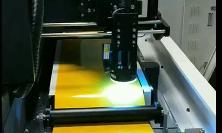
● Imaging and Etching: After the coverlay is laminated onto the substrate, the circuitry pattern is imaged onto the coverlay using photolithography or laser ablation techniques. The areas not covered by the circuitry pattern are then etched away using chemical or plasma etching to expose the metal traces on the substrate.
● Electrical Testing: Once the FPC with Coverlay is fabricated, it undergoes electrical testing to ensure proper connectivity, insulation, and signal integrity. Testing can include visual inspection, continuity testing, and high-voltage testing.
● Assembly and Packaging: After the FPC with Coverlay is electrically tested, it is cut and trimmed to the required size, and any additional components, such as connectors or sensors, are attached to the circuitry. The FPC with Coverlay is then assembled and packaged for shipment or further integration into a larger electronic system.
● Quality Control: Throughout the manufacturing and assembly process, quality control procedures are implemented to ensure the FPC with Coverlay meets the required standards for performance, reliability, and safety. Quality control can include inspection, testing, documentation, and traceability.
Types of FPC Coverlay Materials
Here are some common types of FPC Coverlay materials:
● Polyimide (PI): Polyimide is a popular coverlay material for FPCs due to its high temperature resistance, flexibility, and excellent dielectric properties. PI coverlay is typically used in high-end applications, such as aerospace, medical devices, and automotive systems.
● Polyester (PET): Polyester is another popular coverlay material for FPCs due to its low cost, ease of processing, and good electrical properties. PET coverlay is typically used in consumer electronics, such as smartphones, tablets, and computers.
● Liquid Photoimageable (LPI) Resist: LPI resist is a type of epoxy-based coverlay that is applied as a liquid and cured by UV light. LPI resist offers high resolution, excellent adhesion, and good thermal and mechanical stability. LPI resist is typically used in high-density FPCs, such as camera modules and memory cards.
● Thermoplastic Polyurethane (TPU): Thermoplastic Polyurethane is a flexible and durable coverlay material that offers good resistance to water, chemicals, and abrasion. TPU coverlay is typically used in automotive, industrial, and outdoor applications.
● Thermoplastic Elastomer (TPE): Thermoplastic Elastomer is a soft and flexible coverlay material that offers good adhesion and low-temperature flexibility. TPE coverlay is typically used in wearable electronics, medical devices, and soft robotics.
● Acrylonitrile Butadiene Styrene (ABS): Acrylonitrile Butadiene Styrene is a rigid and impact-resistant coverlay material that is suitable for high-stress applications, such as vibration, shock, and torsion. ABS coverlay is typically used in automotive systems, industrial equipment, and medical devices.
Applications of FPC Coverlay
Here are some common applications of FPC Coverlay:
● Consumer Electronics: FPC Coverlay is used in various electronic products, such as smartphones, tablets, laptops, and digital cameras, to protect the fragile and sensitive components from harsh environments and handling.
● Medical Devices: FPCs with Coverlay are increasingly used in medical devices, such as implantable sensors, pacemakers, and defibrillators, due to their flexibility, biocompatibility, and reliability.
● Automotive Industry: FPC Coverlay is used in automotive applications, such as dashboard displays, infotainment systems, and engine control modules, to withstand the harsh conditions of the engine compartment and the wide temperature range.
● Aerospace and Defense: FPC Coverlay is used in aerospace and defense applications, such as avionics, navigation systems, and communication equipment, due to their lightweight, flexibility, and high reliability.
● Industrial Equipment: FPCs with Coverlay are used in various industrial equipment, such as sensors, controllers, and actuators, due to their ability to handle vibration, temperature variations, and corrosive environments.
● Wearable Electronics: FPC Coverlay is used in wearable devices, such as smartwatches, fitness trackers, and virtual reality headsets, due to their flexibility, low profile, and water resistance.
● LED Lighting: FPC Coverlay is used in LED lighting products, such as backlighting, strips, and panels, to provide insulation, protection, and circuitry routing.
How to Select Right Flex PCB Coverlay ?
Selecting an appropriate flex PCB coverlay requires consideration of several key factors, including:
● Thickness: The coverlay must be thick enough to provide sufficient protection for the underlying circuitry while being thin enough to accommodate any bending or folding that may be required.
● Adhesive Type: The adhesive used in the coverlay should be chosen based on the specific application requirements, such as resistance to moisture, chemicals, or high-temperature environments.
● Dielectric Properties: The coverlay dielectric properties must be compatible with the overall design of the flexible PCB, including its conductor trace thickness and separation distance.
● Surface Finish: The coverlay should be able to bond well with the surface finish of the copper layers to ensure complete encapsulation of the circuitry.
● Manufacturing Process: The manufacturing process used to produce the coverlay may impact its properties, so it is essential to identify a supplier who uses high-quality production processes.
Overall, the appropriate selection of flex PCB coverlay involves a careful analysis of the application requirements, as well as a thorough review of the available material options from reputed suppliers.
Component Feature Openings of FPC Coverlay
Coverlay film offers unique advantages but it also presents certain limitations that should be considered in its application. The coverlay film cannot be developed like LPI solder mask and typically requires cutting or drilling. As a result, it is more suitable for larger constructions with a rectangular shape and small aperture exemptions that must always be drilled around the perimeter. The use of coverlay in flexible PCBs containing SMD components with fine pitch is therefore limited.
Several methods can be used to form the opening of the feature, including drilling, routing, laser cutting, knife cutting, or punching and die sets, or a combination thereof. The appropriate method(s) are determined by the feature’s shape, size, complexity, and the quantity of parts being produced, which may introduce additional issues beyond those encountered with Flex LPI. Specifically, a larger minimum web thickness between adjacent features is necessary to protect the easily damaged thin parts or webs and to make room for sufficient adhesive, thus ensuring proper lamination and encapsulation of copper circuitry. Additionally, a larger minimum annular ring to exposed feature requirement during the lamination process is necessary to allow for material and production tolerances and the potential for adhesive squeeze out.
In designing flexible printed circuit boards with greater density SMT and/or PTH features, it may be necessary to combine several feature holes into bigger “ganged” openings to accommodate the required features. However, this is only feasible if the design permits it. Nonetheless, in certain situations, coverlay can be used in combination with LPI soldermask. The solder mask can fill the gaps between the smaller features, and the coverlay can cover the remaining uncovered areas after the features have been exposed.
Flexible PCB Coverlay vs. Solder Mask Layer ?
For the outer layers of flexible printed circuits, various materials are available for encasement, including polyimide coverlay, flexible solder resist, and flexible solder mask. Although each material has the basic function of covering and protecting the circuitry, they also have unique properties that make them suitable for specific design requirements.

When selecting materials for protecting and isolating circuitry in exposed external layers of flexible printed circuits, polyimide coverlay, flexible solder resist, and solder mask are commonly used. Although their primary function is the same, each material possesses unique features, capabilities, and characteristics that are appropriate for specific design requirements.
Some important distinctions between flexible PCB coverlay and solder mask include:
● Composition: A flexible PCB coverlay is constructed from adhesive and Kapton, a polyimide material. In contrast, a solder mask is a liquid-based substance.
● Dam Sizes: The minimum size for a dam in a coverlay is 10 mils, while a solder mask requires a minimum dam size of 4 mils to prevent molten, liquid solder from flowing from one pad to an adjacent one.
● Trace to Mask Opening: For coverlay, a trace to mask opening as close as 3 mils is possible. On the other hand, using a 3 mil thick solder mask may result in imaging problems and undercutting, requiring a minimum gap of 4 mils between components.
● Application: Coverlay is commonly used to protect flexible parts of the PCB, while solder mask is used in the hard or rigid sections of the board. Use of coverlay throughout a rigid-flexible PCB requires a fang or window opening.
● Pitch Components: Coverlay cannot be used with pitch components, while solder mask does not present such a limitation.
Apply LPI Soldermask and Coverlay to Selected Areas with Stiffeners
In certain rigid-flex PCBs, high component density, complexity, and/or specific requirements may necessitate the use of both coverlay and LPI solder mask for optimal functionality. These materials are applied to distinct regions of the PCB to leverage the benefits of both within one design. Before preparing production files for the PCBs, these materials must overlap within the rigidized area for complete encapsulation of the circuitry and to prevent the development of mechanical stress concentrators in the flexible sections, which may compromise component reliability. While this approach may increase costs, it may be necessary for the rigid-flex design or offer sufficient benefits to justify the additional expense.
Two common approaches to combining coverlay and LPI solder mask are:
● Use LPI solder mask in areas containing rigidized components and coverlay in parts with flexible components.
● Add selective webs of solder mask in the openings of the ganged coverlay.
Questions About Coverlays for Flexible PCBs That Are Often Asked
● In the process of making flexible PCBs, is the opening on the PI film coverlay the same shape and size as the design, or should I change the design to fit what you can make ?
In case you plan to manufacture flexible printed circuit boards (FPCs) through JarnisTech, it may not be necessary to modify your original design. The coverlay opening of a printed circuit board (PCB) is typically square or rectangular. However, some fabricators may recommend oval-shaped openings for compatibility with their mechanical drilling process. At JarnisTech, our drilling processes include punching and mechanical drilling. With punching, the coverlay opening can match your original design if it is square or rectangular.
● What is the distinction between PI coverlay film and PI stiffeners ?
Coverlay serves a similar protective function as solder mask by shielding copper circuits within flexible printed circuit boards (FPCBs). Meanwhile, stiffeners function as reinforced plug-in areas within FPCBs. Typically, FPCB stiffeners are made of materials such as polyimide (PI), stainless steel, or FR4. Coverlay is an essential component for both FPCBs and the flexible part of rigid-flex printed circuit boards. Conversely, stiffeners are only necessary when plug-ins are required, such as with gold fingers.
● Additional Factors to Consider While Using Coverlay
When utilizing coverlay in the production of flexible printed circuit boards (FPCBs), it is important to consider several additional factors. One key aspect to keep in mind is the adhesive type used in the coverlay. The ideal adhesive should be strong enough to bond the coverlay securely to the PCB, yet still flexible enough to allow for bending and movement. Additionally, the thickness of the coverlay should be appropriately selected to ensure that it is compatible with the specific application and circuit board design. Lastly, it is important to consider any additional thermal, electrical, or environmental requirements when selecting the appropriate coverlay material and adhesive.
Future Developments and Trends in FPC Coverlay Technology
Here are some possible developments and trends in FPC Coverlay technology:
● Thinner and more flexible coverlay materials to enable miniaturization of electronic products.
● Integration of advanced materials, such as nanocomposites or graphene, to enhance the mechanical, thermal, and electrical properties of coverlay.
● Introduction of novel manufacturing techniques, such as inkjet printing or laser ablation, to improve the accuracy and efficiency of coverlay deposition.
● Integration of 3D printing technology to produce complex and customized coverlay patterns.
● Adoption of smart coverlay materials that can sense and respond to environmental changes, such as temperature, humidity, or pressure.
● Development of eco-friendly and sustainable coverlay materials that minimize the environmental impact of FPC production.
● Collaboration between FPC manufacturers and end-users to design more efficient and reliable coverlay solutions for specific applications, such as medical devices, automotive systems, or wearable electronics.
● Advancements in FPC Coverlay testing and quality control to ensure the performance and reliability of FPCs in harsh or dynamic environments.
Conclusion
A critical component in flexible printed circuit board (PCB) production, a coverlay film provides insulation and protection to the circuitry of an external layer. Beyond meeting various design requirements, it is essential to distinguish between coverlay and solder mask to simplify flexible PCB design. Comprising a PET or PI laminated film and adhesive, a coverlay safeguards and insulates circuitry in flexible PCBs.
This article offers a thorough overview of coverlay’s use in flexible PCBs, while selecting a one-stop FPC manufacturer like JarnisTech ensures exceptional CAM engineering expertise, high-quality fabrication, and personalized services.
Related Posts:
1. Selecting PCB Laminate Materials: A Comprehensive Overview
2. PCB Copper Trace Width and Space: Everything You Need to Know About Them
3. Which Types are Most Commonly Used in PCB Substrates?
4. What Is Fiberglass PCB and Why Fiberglass Used in PCB Manufacturing?
5. Standard PCB Thickness-Choosing the Correct Thickness for PCB


