Early methods of electronics assembly, such point-to-point construction, were almost entirely supplanted by through-hole technology. Every component on a standard PCB was a through-hole component from the 1950s’ second generation of computers until the mid 1980s, when surface-mount technology (SMT) started to gain popularity. PCBs initially had tracks printed on just one side, then both sides, and finally multi-layer boards.
In order for the components to make contact with the necessary electrical layers, the through holes were converted into plated-through holes, abbreviated PTH for short. Plated-through holes are not necessary for creating component connections when using SMT boards. However, they are still utilized for making interconnections between the layers of the board, and while serving in this capacity, they are more commonly referred to as vias.
Through Hole Technology (THT): What is It?
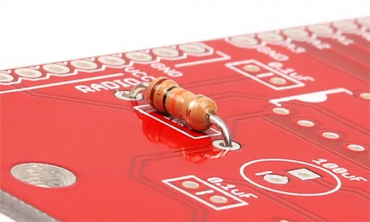
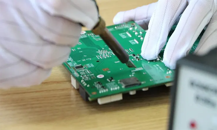
The term “through hole technology” refers to a method for the construction of electronic circuits that involves inserting pin-through hole (PTH) components onto printed circuit boards by way of holes that have been drilled into the boards (PCBs). After that, equipment for wave soldering or re-flow soldering is used to attach the leads, also known as the ends, to the pads on the other side of the board using molten metal solder. The term “through hole assembly” is also used to refer to this process.
Advantages & Disadvantages of THT
Advantages
THT provides superior mechanical connections compared to SMT, making it appropriate for components that are mechanically strained, such as connectors and transformers. Because of the considerable spacing between the holes, manually soldering the constituents is made more simpler. In addition, THT constituents may be simply swapped out for one another, making them an excellent choice for testing and prototyping.
Components made from THT are ideal for use in long-lasting goods that call for strong interlayer connections. THT connections enable components to withstand greater environmental pressures than SMT connections, which only rely on solder on the board’s surface to keep components in place.
As a result, the technique is widely used in goods that are utilized in the military and the aerospace industry and are subjected to extreme circumstances such as high heat, tremendous thrust, or vibrations.
Disadvantages
When utilizing Through Hole, you will need to drill holes in the bare PCB, which is an expensive and time-consuming process. Because the drilled holes on THT boards have to traverse all of the layers, the accessible configuration area on multilayered boards can be reduced as a result. Because the constituent configuration levels of THM are far lower than those of surface mount, the technology is exorbitantly expensive for the majority of applications.
In addition to this, THT requires the use of wave, selective, or manual soldering processes, all of which are considerably less effective and dependable in comparison to the reflow ovens that are utilized in SMT. The most notable difference between THT and SMT is that THT involves soldering on both sides of the board, whereas SMT only requires soldering on one side.
Through-hole Circuit Board Assembly : Why Choose Us
This is used frequently to fulfill the high reliability requirements of the military and aerospace business, as well as in power electronics, which generate a lot of heat. Additionally, this is utilized in some applications to meet the standards of other industries. Other motivating factors include the requirement to use antiquated components or conventional connectors that feature through-holes. THT, which stands for through hole technology, is still a reliable approach for PCB assembly.
However, despite the fact that it results in stronger mechanical bonding, through-hole mounting necessitates a more tedious assembly procedure, which results in an increase in the cost of producing the boards. In order to complete the assembly, component lead needs to be placed through holes and then clipped. There is a possibility that the component leads will need to be pre-formed. It may be necessary to use solder tacking or to bend the legs of the component in order to keep the parts in place while the soldering is being done.
No matter what your industry, you can rely on our professional experience and knowledge regarding the best mounting technology to use for your specific needs. In order to guarantee the best possible outcomes, our THT experts have undergone extensive training in accordance with IPC-A-160 requirements.
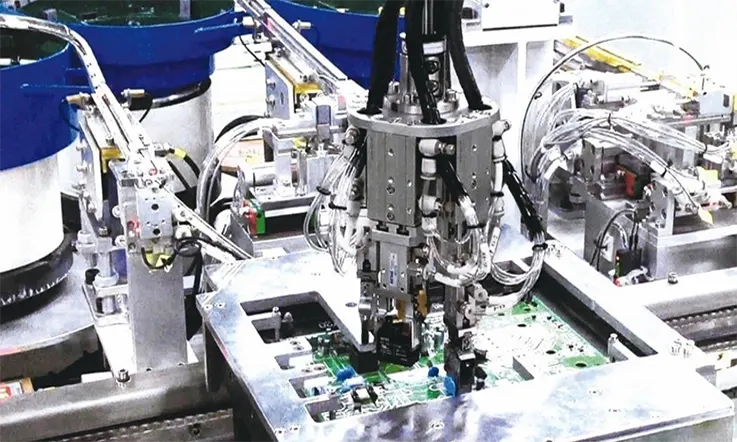
Our extensive capabilities range from manual assembly and hand soldering all the way up to automated soldering of radial and axial components. Hand assembly and manual soldering are also included in this category. For the most majority of THT component soldering, selective soldering machines are the method of choice. A compact three-axis moveable wave solder head is at the core of a selective soldering machine. The machines pre-heat the printed circuit board (PCB) and individually solder each component lead at a rate that is several times faster than can be done manually, with a consistency that can only be achieved by computer control.
Each solder joint can have its own individualized programming for the optimal rate of solder wave application, dwell time, and solder wave withdrawal. Because the geometry of the solder wave application does not change, it is possible to achieve absolute reproducibility without subjecting the operator to fatigue.
In addition, you can utilize our in-house auxiliary services, such as conformal coating, for the completion of your product.
Components Types of Through Hole Technology
Active and passive components can be roughly differentiated from one another when discussing the components of plated through hole circuit boards, just as is the case with all other types of components. The mounting process for each variety of component on the board is exactly the same. It is necessary for the designer to incorporate through-holes into the PCB layout. These hols should be surrounded by pads on the surface layer for soldering purposes.
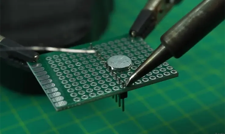
The procedure of mounting components using through-holes is very straightforward; all that is required is to place the component leads into the holes and then solder the exposed lead to the pad. Components on plated through-hole circuit boards are typically large and sturdy enough to allow for straightforward hand soldering. Because the component leads on passive through-hole components can often be fairly long, it is common practice to clip them down to a more manageable length before mounting them.
Active Through-hole Components
If you think back to the integrated circuits you used in your previous electronics lessons, you’ll probably remember that they came in either a dual-inline package (DIP) or a plastic DIP (PDIP). In the course of proof-of-concept development, these components are typically seen installed on breadboards; nevertheless, in actual PCBs, they are utilized rather frequently. Active through-hole components, such as op-amp packages, low-power voltage regulators, and a great deal of other typical components, frequently come in the DIP package.
Other components, such as transistors, greater power voltage regulators, quartz resonators, higher power LEDs, and many others, may come in a zig-zag in-line package (ZIP) or a transistor outline (TO) package. These additional packages mount to a PCB in a manner that is analogous to that of axial or radial passive through-hole technology.
The invention of through-hole components occurred at a time when designers were more concerned with mechanically reliable electronic systems and less concerned with aesthetics and signal integrity. Less emphasis was placed on minimizing component size, and signal integrity issues were not a priority. Later, as power consumption, signal integrity, and board space constraints were paramount, designers were compelled to use components with the same electrical capability but in a smaller packaging. This is the purpose of surface-mount components.
Passive Through-Hole Technology
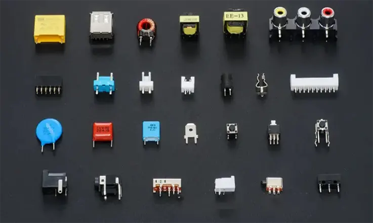
The two possible packaging types for passive through-hole components are radial and axial. Electrical leads on an axial through-hole component follow the axis of symmetry of the component. Consider a basic resistor. Its cylindrical axis is traversed by the electrical lines. The same mounting method is used for many capacitors, inductors, and diodes. Some through-hole components, such as high power resistors, come in rectangular packages with a lead wire running down the length of the package; not all through-hole components come in cylindrical packages.
On the other hand, radial components have electrical leads that stick out of one end of the component. Many big electrolytic capacitors are packaged in this manner, which makes it possible for them to be mounted to a board by putting the lead through a hole pad while also allowing them to occupy a smaller amount of area on the circuit board. Other components such as switches, LEDs, tiny relays, and fuses come packaged as radial through-hole components.
Get the Assistance You Need to Choose the Proper Components
The question now is, what kind of component package should you employ for your circuit board? The correct response is that it is dependent on the design, the quantity of boards that need to be constructed, and the production process that will be employed. You are in luck since the PCB contract manufacturer you work with can provide you with some good assistance in finding the answers you need. These individuals have spent years guiding designers through the process of selecting the most appropriate components for their designs using the following tools and resources:
● Component engineers can assist you in making choices about parts depending on the requirements of the application.
● Design engineers are needed to assist in changing parts and making alterations to the circuitry so that the design will have the highest possible electrical performance.
● Engineers in manufacturing can aid in the selection of suitable components, leading to more streamlined manufacturing procedures.
● During times of supply chain shortages, it is the responsibility of procurement professionals to locate the highest quality original parts at the most competitive costs.
● At Jarnistech we has been assisting customers with the component selection process for well over 20 years, and we have earned a reputation for providing quality service in this time period. We are able to assist you in determining which through-hole components will be the most suitable for your design while simultaneously answering any queries that you may have regarding the design or layout of these parts.
Through Hole Technology Process vs. Surface Mount Technology Process
Assembly using through hole technology (also known as THT) has been around for the better part of a century (since the 1940s), and it has been demonstrated to be extremely reliable, capable of securing large components, and able to maintain connectivity in the face of high power and high temperatures. Surface mount technology, often known as SMT, was developed to accept smaller and lighter components, and it performs a good job of doing so. In addition to being more cost-efficient than THT, SMT allows for more complicated trace routing to be implemented.
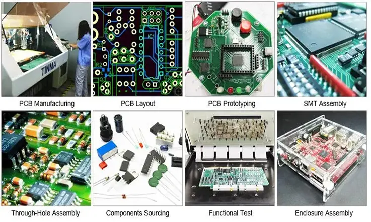
Whatever the manner of assembly, J-STD-001, J-STD-002, and J-STD-003 standards for solder joint quality must be followed. Whether you use SMT or THT for assembly, the fundamental steps are roughly the same. The fundamental steps in printed circuit board assembly (PCBA) are as follows:
● Preparing the Bare Circuit board from the manufacturing process.
● Component position.
● The soldering of parts.
● Verification and correction.
● Cleaning the PCB board.
● Depanelization.
The difference between THT and SMT assembly is in how the components are placed and soldered.
Through Hole Technology Process Steps
Component placement: THT requires the leads or pins of the components to be put through the board.
Inspection and correction: Any placement mistakes will be fixed here.
Wave soldering: A “wave” of solder is passed over one side of the circuit board when wave soldering is being performed. During the course of the wave, the through-hole components are soldered concurrently as the board is moving.
Surface Mount Technology Process Steps
Solder paste application: In surface-mount technology (SMT), the components are held in place with an initial layer of solder paste before they are soldered.
Component mounting: Components are mounted on footprints made up of conductor pads that will be soldered together to provide electrical connections.
Reflow soldering:The process of reflow soldering is carried out in an oven, which can reach temperatures as high as 235 degrees Celsius.
Summary-What Is the Best Approach for You?
It can be difficult to determine which setup approach will provide your board its best chance of success in bringing your idea to life. Over ninety percent of printed circuit boards (PCBs) manufactured today employ surface mount technology; but, which of the available options is the most suitable for you? When compared to through-hole technology, surface mounting almost universally exhibits higher levels of efficiency and is more cost-effective. It enables a lightweight design while at the same time allowing for a high component density.
The requirement for THT mounting will however persist due to special mechanical, electrical, and thermal considerations, guaranteeing its continuous significance for the foreseeable future.
Are you unsure whether through-hole printed circuit boards are the best option for your project? Give us a call or send an email to [email protected] with your ideas. Our knowledgeable representatives can assist you in determining the best type of printed circuit boards for your project.
Related Posts:
1. What Is PCB Etching and How to Make a perfect PCB Etching?
2. The Best PCB Panelization Guide
3. The Importance of 3D Printed PCBs in Modern Electronics Production
4. Understanding PCB Delamination: A Comprehensive Guide
5. The Best Backplane Printed Circuit Boards Factory
7. Detail Talk Surface Mount Technology