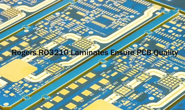
In today’s advanced electronics, achieving optimal performance at high frequencies often hinges on the selection of specialized substrate materials. Rogers RO3210 has emerged as a notable choice for such exacting requirements, offering a distinct set of characteristics suited to complex RF, microwave, and other challenging applications.
This guide provides a focused exploration of Rogers RO3210 Printed Circuit Boards. We will examine its material composition, electrical and physical performance attributes, layout considerations, diverse applications, and the nuances of its fabrication, testing, and sourcing. The information is presented for technical professionals across sectors like high-frequency electronics, medical technology, communications, military, and industrial manufacturing, aiming to offer valuable insights in a clear, professional, and accessible manner. We trust this condensed overview will serve as a useful resource.
Introduction to Rogers RO3210 PCB Laminates: The Foundation
Imagine crafting a high-performance race car; every component is selected with purpose. Consider the chassis – its core structure. In high-frequency electronics, the Printed Circuit Board laminate serves a similar foundational purpose. It’s far more than a mounting surface; it’s an intricate part of the circuit, profoundly influencing every signal’s journey. Venturing into RF and microwave development, understanding the substrate’s characteristics is fundamental to predicting performance. Let’s explore the substance of Rogers RO3210 PCB Laminates, appreciating the precise composition that makes them a reliable choice for many high-frequency systems. Understanding this material is the first step; realizing its full potential often requires equally advanced manufacturing and assembly expertise.
What are Rogers RO3210 PCB Laminates? The PTFE/Ceramic Advantage?
Rogers RO3210’s identity is rooted in a clever combination of materials, each bringing specific attributes. Think of it as a carefully orchestrated marriage of materials, formulated to overcome the limitations of using any single component alone. This blend offers a performance profile resonating deeply with the needs of those working with RF technology.
Understanding PTFE Laminates & Ceramic Filled Laminates
The story of the RO3210 Material begins with Polytetrafluoroethylene (PTFE). Technical professionals admire PTFE Laminates for their remarkably low electrical loss – signals pass with minimal energy dissipation, a highly desirable quality for high-frequency work. However, pure PTFE can be mechanically ‘soft’ and tends to expand and contract noticeably with temperature changes, creating challenges during manufacturing and affecting circuit stability.
This is where the ‘Ceramic’ part of PTFE/Ceramic Laminates enters. Rogers introduces specialized ceramic fillers into the PTFE matrix. These fillers act as a stabilizing force within the Ceramic Filled Laminates, providing necessary mechanical rigidity and substantially lowering the material’s thermal expansion coefficient. This makes it behave more predictably during soldering and operation. This fusion allows RO3210 to retain PTFE’s electrical allure while offering a much more robust and stable physical structure.
The Role of Woven Glass Reinforcement in RO3210 Substrates
To further enhance structural integrity, Rogers incorporates Woven Glass Reinforcement into the RO3210 Substrates. This acts like an internal framework, providing significant strength and ensuring the material maintains its shape. This reinforcement contributes significantly to the exceptional Dimensional Stability RO3210 is known for. For PCB Fabrication houses dealing with multi-layer boards or fine-line features, this stability means tighter tolerances, more precise layer-to-layer registration, and potentially improved manufacturing yields. It gives the board requisite structural support.
Key Benefits & Unique Selling Points of RO3210 Material
RO3210’s sophisticated formulation translates into tangible benefits for specialists in circuit creation and manufacturing, addressing persistent high-frequency challenges. Key advantages encompass:
| Benefit | Specification Behind It | Technical Impact |
| Signal Integrity | Dissipation factor 0.0027 @10GHz | Low signal loss for RF/microwave circuits |
| Dimensional Stability | Woven glass reinforcement | Minimizes board warpage during multilayer fabrication |
| Design Predictability | DK stability ±0.3 | Simulation accuracy, reduced tuning cycles |
| Manufacturing Efficiency | Thermal expansion 32 ppm/°C | Reduced via cracking and misalignment |
| Environmental Robustness | Moisture absorption 0.02% | High reliability in humid or varying temperature environments |
●Predictable and Reliable Performance: Ensuring consistent operational outcomes for your High Frequency PCBs.
●Exceptional Signal Preservation: A direct result of its very Low Loss Material characteristics.
●Enhanced Design Accuracy: Stemming from its stable Dielectric Constant (DK).
●Improved Manufacturability and Durability: Resulting from enhanced mechanical properties for High Performance PCB projects.
●Backed by Industry Expertise: As a product from Rogers Corporation.
Why Choose RO3210 High Frequency PCBs?
Opting for RO3210 High Frequency PCBs means investing in predictable, reliable performance. Its standout feature is its exceptionally Low Loss Material characteristic, which preserves signal power—particularly advantageous in battery-powered devices, sensitive receivers, or high-power transmitters. The stable Dielectric Constant (DK) ensures that simulation results align more closely with actual circuit behavior, reducing the number of development iterations required. Additionally, its superior mechanical strength supports a smoother manufacturing process and yields a more robust final product. RO3210 is a strategic choice for any High Performance PCB application where reliability is critical and failure is not an option.
Rogers Corporation Products: A Legacy in Advanced PCB Materials
Specifying RO3210 connects you to Rogers Corporation’s deep expertise. With a long-standing track record in developing Advanced PCB Materials, Rogers Corporation Products offer a built-in assurance of quality and reliability. Their extensive support resources, including detailed data sheets for each Rogers PCB Material, equip technical professionals with the critical information needed for successful design and implementation. This legacy of innovation and precision has earned widespread trust, ensuring their materials meet the stringent demands of High Frequency PCB applications and reinforcing their leadership in the industry.
RO3210 vs. Alternatives: A Comparative Analysis (RO4003, FR4)
Informed material selection involves understanding the landscape. How does RO3210 stack up against other common choices a circuit layout specialist might consider?
RO3210 vs RO4003 & RO3210 vs FR4
First, FR4: for high-frequency work, the RO3210 vs FR4 comparison is stark. While FR4 is cost-effective for many circuits, its electrical losses become prohibitive in the gigahertz range. Its DK can also vary significantly, making controlled-impedance designs challenging. For serious RF work, FR4 typically isn’t a contender.
| Material | DK @ 10GHz | Dissipation Factor | Thermal Expansion (Z-axis) | Key Feature |
| RO3210 | 10.2 ± 0.5 | 0.0027 | 32 ppm/°C | High-frequency, low-loss, ceramic/PTFE |
| RO4003C | 3.38 ± 0.05 | 0.0027 | 46 ppm/°C | Balanced performance, easier to process |
| Standard FR4 | ~4.5 (variable) | ~0.020 – 0.030 | 70+ ppm/°C | Low-cost, but not suitable for GHz range |
A more nuanced discussion involves RO3210 vs RO4003. RO4003, another well-regarded Rogers material, is a hydrocarbon/ceramic system known for easier processing, similar to FR4. While RO4003 delivers good high-frequency performance, RO3210 generally offers even lower dielectric losses. This makes RO3210 preferred where every fraction of a decibel matters or for very high (millimeter-wave) frequencies. The trade-off often lies here: RO3210 provides a potential performance edge, while RO4003 offers a more familiar processing path. The decision often hinges on specific performance targets and available manufacturing capabilities.
Understanding these material distinctions is foundational. However, translating a design based on a high-performance material like RO3210 into a reliable finished product requires specialized PCB Fabrication and assembly expertise. RO3210’s theoretical advantages are fully realized only through precise manufacturing that accommodates its unique characteristics. At JarnisTech, we possess extensive experience and dedicated equipment for processing Rogers RO3210 materials, offering comprehensive services from prototype to volume production, including PCB assembly. We help you navigate manufacturing complexities with these advanced substrates, ensuring your design intent is perfectly executed.
Deep Dive: RO3210 Electrical Properties & Signal Integrity
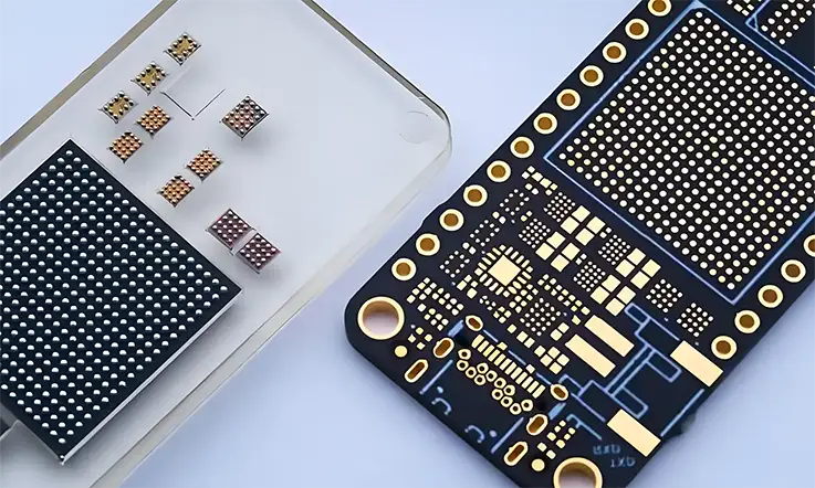
For any High Frequency PCB, the electrical behaviour of its substrate acts as the unseen conductor, orchestrating the performance of the entire system. Signals pulsing in the gigahertz range behave less like simple currents and more like waves, extraordinarily sensitive to the medium they travel through. Their speed, strength, and clarity are all shaped by the substrate.
Here, we delve into the specific electrical characteristics of Rogers RO3210. We will explore how its fundamental properties contribute to achieving excellent Signal Integrity – the art of preserving a signal’s form and timing from its origin to its destination. This understanding is foundational for anyone involved in Communications High-Tech Enterprise or the development of advanced RF systems. Achieving this level of performance consistently in manufactured boards relies not only on a deep understanding of these material properties but also on meticulous fabrication and assembly processes.
Electrical Parameters: DK & Dissipation Factor
When evaluating any high-frequency material, two figures offer profound insights into its interaction with electrical fields. This section focuses on:
●The Dielectric Constant (DK): Its stability and influence on signal behavior.
●The Dissipation Factor (Df) / Loss Tangent: Its direct connection to signal loss and system efficiency.
Achieving Stable Dielectric Constant (DK) Across Frequencies
The Dielectric Constant (DK), technically known as relative permittivity (Er), governs the speed at which an electrical signal moves within the material and directly affects the characteristic impedance of transmission lines. For High Frequency Circuits, a lower DK can often be beneficial, but what holds even greater weight is stability. Rogers RO3210 exhibits a remarkably Stable DK – typically around 10.2, although consulting the specific RO3210 Data Sheet for the precise grade and frequency is always a sound practice. This stability extends across a wide frequency spectrum and through varying temperatures. This predictability is a tremendous asset for those crafting circuits, allowing for the creation of RF Circuits and Microwave Circuits that perform as anticipated, often reducing the need for extensive post-production adjustments. It greatly simplifies the task of achieving precise Impedance Control, a characteristic that skilled fabrication can help maintain throughout production.
Understanding Low Dielectric Loss & Loss Tangent
The Dissipation Factor (Df), or Loss Tangent, provides a measure of how much signal energy the dielectric material absorbs and turns into heat. Think of it like a sound wave fading in a heavily padded room – you want your signal to travel with minimal absorption. In high-frequency systems, reducing this loss is frequently a primary objective. Rogers RO3210 presents a very Low Dielectric Loss, one of its defining RO3210 Advantages. This translates directly into more robust signals at the receiving end, less heat build-up (a particular concern for Power Amplifiers), and improved overall system efficiency. For components like Filters and Couplers, and within sensitive receiver front-ends, specifying a Low Loss Material like RO3210 often becomes a prerequisite for success.
Preserving Signal Integrity with Rogers RO3210 PCB Layouts
Preserving signal integrity – ensuring signals arrive at their destination without distortion or undue delay – involves several layout considerations where the RO3210 substrate plays a supporting part. Key aspects include:
●Achieving Precise Impedance Control: To maintain stable and predictable signal pathways.
●Leveraging Copper Characteristics: Such as low-profile copper to minimize insertion losses.
●Minimizing Crosstalk: Through careful layout and uniform material properties.
Achieving Precise Impedance Control for High Speed PCB
Every pathway on a PCB exhibits a characteristic impedance. When there are mismatches in impedance along a signal’s route, reflections occur. These reflections can corrupt data and degrade performance. RO3210’s consistent DK makes the task of achieving precise Impedance Control much more manageable. Those responsible for circuit layout can calculate trace dimensions and spacing with a higher degree of confidence, knowing the substrate will behave predictably. This forms a fundamental discipline for any High Speed PCB development. This confidence in material predictability is further enhanced when partnered with a PCB Manufacturer capable of consistently achieving the fine tolerances demanded by such precise impedance specifications during PCB Fabrication.
Low Profile Copper & Its Impact on Signal Transmission
While RO3210’s dielectric performance is exceptional, the copper foil it’s paired with also influences outcomes. Utilizing Low Profile Copper helps to lessen the “skin effect” at high frequencies. At these speeds, current tends to flow mainly along the outer surface (or ‘skin’) of a conductor. Smoother copper profiles offer a less resistive path, reducing losses and further enhancing the quality of Signal Transmission. Many RO3210 Laminates can be specified with these advantageous low-profile copper options. Selecting the appropriate copper profile, and ensuring its integrity through the manufacturing stages, contributes to optimizing overall Signal Transmission.
Minimizing Crosstalk in RF Circuits & High Frequency Circuits
Crosstalk, the undesired coupling of energy between neighbouring traces, presents an ongoing challenge in densely packed High Frequency Circuits. The stable material properties of RO3210, when combined with careful PCB Design and Layout practices, can help keep this interference in check. Its reliable DK permits accurate modelling and implementation of spacing rules needed to maintain isolation, both in analog RF Circuits and within High Speed Digital PCB designs.
RO3210 Data Sheet: Decoding Electrical Specifications
The RO3210 Data Sheet, available from Rogers Corporation, serves as an indispensable reference document. It offers a wealth of detailed information covering all electrical and physical parameters – DK (often presented at multiple frequencies, including 10 GHz), Df, thermal behaviour, and mechanical data. Anyone performing circuit simulation or planning a layout with this material should study this document with care. It provides the ground-truth values needed for accurate modelling and a thorough understanding of the material’s performance envelope.
While the RO3210 Data Sheet provides the theoretical foundation, translating these precise specifications into a consistently performing physical RO3210 Circuit Board requires expert manufacturing. This involves controlled processes for lamination, drilling, plating, and etching that respect the material’s unique properties, ensuring the finished board truly reflects the datasheet values.
Understanding RO3210 Mechanical & Thermal Performance
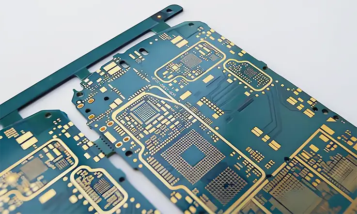
While the intricate dance of electrons and electromagnetic fields often captures the spotlight in high-frequency discussions, we must not overlook the physical realities of the circuit board. A substrate must not only guide signals faithfully but also endure the rigours of its creation and its operational environment. How a material behaves under physical stress and how it handles heat are fundamental considerations, particularly for those in PCB Manufacturing, assembly, and anyone aiming for long-term product reliability. Let’s examine the physical constitution of Rogers RO3210 and its behaviour in the face of thermal challenges, aspects especially relevant for the High Precision PCB Circuit Board Industry and Military Equipment Manufacturing. Successfully harnessing these physical attributes in a final product, however, hinges on precise manufacturing and assembly practices.
Mechanical Robustness & Dimensional Stability
A material’s ability to withstand handling, maintain its form, and resist environmental changes directly influences manufacturing success and product lifespan. Key aspects of RO3210’s mechanical performance include:
●Resilience under Physical Stress: How it endures fabrication and assembly processes.
●Exceptional Dimensional Stability: Maintaining precise form through temperature changes and stress, benefiting High Precision PCB Circuit Board Industry applications.
RO3210 Characteristics under Physical Stress
Thanks to its integrated ceramic fillers and the underlying Woven Glass Reinforcement, Rogers RO3210 displays commendable mechanical strength and rigidity. This means it can better withstand the pressures involved during lamination, the vibrations during drilling, and the stresses of the assembly line without undue warping or structural compromise. Its Dimensional Stability stands out as a significant attribute. This refers to the material’s ability to retain its original dimensions – its size and shape – when subjected to temperature fluctuations or the stresses of PCB Manufacturing. For projects demanding fine lines, tight spaces, and precise layer-to-layer alignment, this stability is a genuine asset. It translates into more accurate feature replication, better registration in multi-layer builds, and potentially higher production yields. These RO3210 Properties build confidence in its suitability for complex hardware, especially when processed by a PCB Manufacturer adept at handling its unique characteristics.
RO3210 Thermal Management Strategies
With increasing power densities in compact electronic devices, effective heat management is a pronounced challenge. For RO3210, this involves understanding:
●Its Inherent Thermal Conductivity: And how it compares to other materials.
●Proactive Design & Assembly Techniques: For dissipating heat in High-Power RO3210 Applications.
Thermal Conductivity Explained
Thermal Conductivity is a measure indicating how readily a material allows heat to pass through it. While Rogers RO3210 possesses better thermal conductivity than many un-filled PTFE materials, it generally doesn’t transfer heat as effectively as substrates like alumina ceramics or dedicated metal-core PCBs. It’s helpful to approach RO3210 Thermal Management with a clear understanding of this characteristic.
Design Techniques for High-Power RO3210 Applications
When working with High-Power RO3210 Applications, such as Power Amplifiers or control boards within Industrial Large Equipment Manufacturing, proactive thermal solutions are often necessary. Those involved in circuit layout and system integration can employ several techniques. Creating arrays of thermal vias – small, plated holes connecting copper layers – can act like small chimneys, helping to channel heat away from components towards larger copper planes or external heat sinks. Employing thicker copper layers or attaching dedicated heat sinks directly to heat-generating components are also common approaches. Careful component placement – avoiding clustering high-power parts – and thoughtful board layout contribute substantially to effective thermal dissipation, allowing for reliable operation even under demanding thermal loads.
These design techniques provide a roadmap for managing thermal loads. However, their successful implementation – from precise drilling and plating of thermal vias to careful component mounting for optimal heat transfer during PCB Assembly – relies heavily on the capabilities of your manufacturing partner. At JarnisTech, we specialize in translating such thermally considerate designs into robustly manufactured realities.
Strategic Rogers RO3210 PCB Design & Engineering
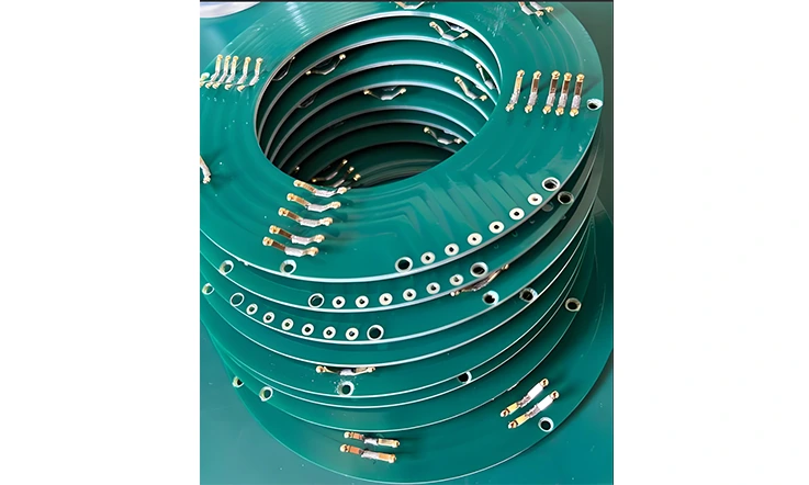
Transforming an innovative concept into a tangible, high-performing Rogers RO3210 PCB is a journey that unfolds primarily on the digital canvas of the layout tool. This is where the theoretical meets the practical, where the remarkable potential of RO3210 is either harnessed or hindered. Undertaking Rogers RO3210 PCB Design successfully requires more than just connecting points; it demands a deep appreciation for the behaviour of high-frequency signals, an understanding of the material’s nuances, and foresight into the manufacturing process. It’s about thoughtfully shaping the copper pathways to guide electromagnetic waves with precision and clarity.
Best Practices for Rogers RO3210 PCB Design & Layout
Adopting proven methodologies during the PCB Design and Layout phase substantially elevates the likelihood of achieving desired performance, especially with specialized materials like RO3210. Core practices involve:
| Design Practice | Description | Impact on Performance |
| Trace Length Minimization | Short, direct traces reduce delay and reflection risk | Improves signal integrity |
| Curved Traces over Right Angles | Reduces impedance discontinuities | Minimizes signal reflection and EMI |
| Solid Ground Planes | Continuous reference plane for return currents | Lowers loop inductance, improves EMC |
| Controlled Impedance Routing | Maintains consistent transmission line characteristics | Ensures signal fidelity |
| Careful Via Design | Avoid unnecessary vias, use back-drilling if needed | Prevents signal distortion due to stubs |
●Adherence to High Frequency PCB Design Guidelines: Establishing a solid foundation for signal integrity.
●Specific RF Circuit Design Considerations: Addressing the unique behavior of radio frequency signals.
●Accurate Translation to Manufacturing Data: Ensuring design intent is perfectly captured in RO3210 Gerber Files.
●Validation through PCB Prototyping: Mitigating risks and refining performance before full-scale production.
High Frequency PCB Design Guidelines
Foundational High Frequency PCB Design Guidelines provide a solid starting point. These principles often include practices like keeping signal paths as direct and short as possible, employing curved traces instead of sharp right-angle bends to minimize reflections, establishing robust and unbroken ground planes, managing via transitions with care to maintain impedance continuity, and meticulously planning signal return paths. When applied to RO3210, these guidelines take on added weight, as even minor deviations can have noticeable effects at the higher frequencies where this material often operates.
RF Circuit Design Considerations
Moving into specific RF Circuit Design Considerations introduces further layers of complexity. Here, meticulous attention must be paid to impedance matching between components and transmission lines to ensure maximum power transfer and minimal reflections. Understanding and mitigating parasitic capacitance and inductance – those unseen effects that arise from physical layout – becomes a central task. Shielding sensitive circuit sections to prevent interference and managing potential electromagnetic emissions are also standard practices. Accurately modelling the RO3210 material within simulation tools is a frequent necessity before committing to a physical layout, allowing for virtual testing and refinement.
From Schematic to Reality: RO3210 Gerber Files & Prototyping
The path from a finalized schematic to a physical board involves two distinct stages:
●Creating Flawless RO3210 Gerber Files: The blueprint for fabrication.
●The Value of PCB Prototyping with RO3210: For design validation and risk mitigation.
Creating Flawless RO3210 Gerber Files
RO3210 Gerber Files serve as the universal language, communicating the intricate details of the layout to the fabrication house. Absolute accuracy and clarity are paramount. The individuals preparing these files must ensure their layout software is correctly configured and that the output clearly defines every trace, pad, drill hole, and dimensional tolerance. Any ambiguity can lead to manufacturing errors. It is also good practice to include specific fabrication notes tailored to RO3210, highlighting any special processing requirements. Engaging with your fabricator early, like JarnisTech, for a Design for Manufacturability (DFM) review of your RO3210 Gerber Files can further prevent costly errors downstream.
The Importance of PCB Prototyping with RO3210
Given the subtleties of high-frequency behaviour and the investment involved with specialized materials, PCB Prototyping represents a prudent validation step. Building a small number of RO3210 PCB prototypes offers the opportunity to physically test and measure the circuit’s performance, comparing it against simulations and requirements. This allows for the identification and correction of any unforeseen issues before launching into full-scale production, ultimately saving both time and resources. Many fabricators provide Quick Turn PCB services to facilitate this rapid iteration. At JarnisTech, our RO3210 PCB prototyping service goes beyond speed; we offer valuable feedback on the manufacturability of your design with RO3210, helping to refine it for optimal production and performance before you commit to larger volumes.
Leveraging High Frequency PCB Technology in Your Designs
Working effectively with Rogers RO3210 means engaging with the broader spectrum of High Frequency PCB Technology. This involves familiarity with different transmission line structures like microstrip and stripline, understanding their optimal applications, and potentially incorporating advanced techniques such as ‘via stitching’ or ‘via fencing’ for enhanced isolation, or ‘back-drilling‘ to remove unused portions of vias (stubs) that can affect signal integrity at very high frequencies. Staying informed about these available techniques empowers those creating the circuits to extract maximum performance from the chosen RO3210 material.
| High-Frequency Technique | Application | Technical Benefit |
| Microstrip | Signal trace on top layer over ground plane | Easier access, used in RF sections |
| Stripline | Embedded trace between two ground planes | Superior isolation and noise immunity |
| Via Stitching | Vias placed around traces and zones | Reduces EMI, improves ground continuity |
| Via Fencing | Similar to stitching but denser, forms isolation wall | Electromagnetic shielding and signal isolation |
| Back-Drilling | Removes unused via stubs | Prevents reflections at very high frequencies |
| Controlled Impedance Tolerance | ±10% or tighter for RF lines | Matches simulated performance, lowers return loss |
However, these advanced design techniques often require equally advanced manufacturing capabilities to be implemented correctly and reliably. Precision in layer registration, specialized drilling for back-drilling, and controlled plating processes are just a few examples of the manufacturing expertise needed.
Mission-Critical Applications: Where RO3210 Excels
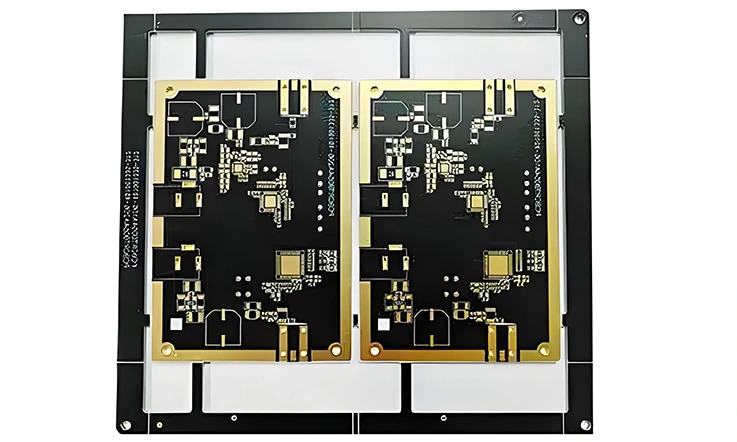
A material truly reveals its character when subjected to demanding, real-world conditions – situations where consistent performance is not just desired, but an absolute necessity, and where the consequences of underperformance can be substantial. Rogers RO3210 distinguishes itself in such environments. Its unique combination of electrical fidelity and mechanical steadfastness has made it a material of choice for a variety of high-stakes sectors. These are fields where electronic systems must operate flawlessly, often under challenging circumstances, pushing the boundaries of what’s possible. Let’s explore some of these application areas where Rogers RO3210 PCB technology demonstrates its capabilities – capabilities that are consistently brought to life through expert PCB Fabrication and meticulous PCB Assembly.
Aerospace & Defense PCB: Ultimate Reliability
In the aerospace and defense sectors, electronic systems face extreme operational challenges. For Aerospace & Defense PCB applications using RO3210, the focus is on:
●Performance in Extreme Environments: Ensuring functionality under intense vibration and temperature swings.
●Precision for Demanding Hardware: Such as in Radar Systems PCB and complex Military Equipment Manufacturing.
●Long-Term Dependability:Required for Satellite Communication PCB and aligning with overall High Reliability PCB standards.
RO3210 in Radar Systems PCB & Military Equipment Manufacturing
Radar Systems PCB applications, whether for surveillance, navigation, or targeting, operate with signals that demand exceptional clarity and timing. The stable dielectric constant and low loss profile of RO3210 are highly beneficial for the antenna feeds and signal processing boards at the heart of these systems. This consistency helps ensure that phased arrays can be steered accurately and that faint return signals are not lost in material noise.
In the broader scope of Military Equipment Manufacturing, where devices must be exceptionally robust and dependable, RO3210 provides a substrate that can withstand tough physical conditions while maintaining its electrical performance, contributing to the overall dependability of the apparatus. Achieving such resilience and precision in the final RO3210 Circuit Board consistently requires manufacturing processes attuned to the nuances of high-reliability applications.
Satellite Communication PCB & High Reliability PCB Needs
For Satellite Communication PCB platforms, the operational environment presents a unique set of trials: the vacuum of space, intense thermal cycling from sunlight to shadow, and the impossibility of performing maintenance once deployed. These systems must function without fault for many years. RO3210’s low signal loss is a distinct advantage here, as every bit of power is precious when transmitting or receiving signals over vast cosmic distances. Its inherent stability contributes to the long operational lifespans required, aligning perfectly with the stringent demands for High Reliability PCB in these orbital assets.
Telecommunications & High-Tech RF Applications
The drive for faster, more connected experiences fuels innovation in Telecommunications. RO3210 supports these advancements through its application in:
●Wireless Infrastructure: Including next-generation base stations, RF Modules, and LNBs.
●Specialized RF Components: Enabling High Performance RF Applications like advanced Filters, Couplers, and Power Amplifiers.
●Core Network Support: For robust Communication Systems PCB and High-Speed Data Links.
Powering Wireless Base Stations, RF Modules & LNBs
Modern Wireless Base Stations, particularly those enabling 5G and looking towards future 6G networks, operate at progressively higher frequencies and often involve increased power densities. RO3210 is a common selection for their power amplification stages and intricate antenna systems. Compact RF Modules, which pack significant functionality into small footprints, also benefit from RO3210’s ability to support dense, high-performance circuitry. In the realm of satellite television reception, LNBs (Low Noise Block) converters depend on very low-loss materials like RO3210 to effectively capture and amplify weak signals from distant satellites.
High Performance RF Applications: Filters, Couplers, Power Amplifiers
Many specialized High Performance RF Applications require components built to exacting specifications. RO3210 is a fitting substrate for constructing high-Q Filters that precisely select desired frequencies, accurate Couplers that distribute signals with minimal disturbance, and efficient Power Amplifiers that boost signal strength without introducing undue distortion or loss. Its material properties allow these components to achieve their intended performance levels.
Enabling Communication Systems PCB & High-Speed Data Links
Beyond individual components, RO3210 supports the broader infrastructure of modern communications. It provides the necessary signal integrity for network backbones, advanced Communication Systems PCB, and the high-capacity High-Speed Data Links that shuttle vast amounts of information around the globe, ensuring that data arrives clearly and quickly. The successful deployment of these diverse telecom solutions often depends on the precise fabrication and assembly of the underlying Rogers RO3210 PCB, ensuring signal integrity is maintained from component to system level.
Medical Device OEM & Automotive Sensors
Beyond communications and defense, RO3210’s characteristics support innovation in other sophisticated fields:
●Medical Technology: Enhancing clarity and sensitivity in Medical Imaging and diagnostics for Medical Device OEM organizations.
●Automotive Systems: Enabling reliable Automotive Radar and other High-Frequency Automotive Sensors.
RO3210 for Medical Imaging & Diagnostics
Medical Device OEM (Original Equipment Manufacturer) organizations often utilize high-frequency signals in advanced Medical Imaging modalities, such as Magnetic Resonance Imaging (MRI) systems, and in various diagnostic tools. RO3210’s low signal loss and stable electrical properties can contribute to the acquisition of clearer, higher-resolution images and support the development of more sensitive diagnostic instruments, ultimately aiding in patient care.
Automotive Radar & High-Frequency Automotive Sensors
The modern vehicle is rapidly transforming into a sophisticated electronic platform. Automotive Radar systems, typically operating around 77 GHz for Advanced Driver-Assistance Systems (ADAS) and the progression towards autonomous driving, are a prime example. RO3210 is a strong material candidate for these High-Frequency Automotive Sensors. Its performance characteristics enable the reliable detection and tracking of objects, which is fundamental for collision avoidance and enhanced situational awareness on the road. The consistent manufacturing of RO3210 PCB to tight tolerances is a contributing element in the dependable performance of these safety-related automotive systems.
Industrial & Test and Measurement PCB Solutions
In demanding Industrial environments where control systems require high-frequency precision, and within sophisticated Test and Measurement PCB setups where signal purity and measurement accuracy are non-negotiable, RO3210 offers a robust and dependable substrate solution. Its stable characteristics ensure that measurements are repeatable and that industrial controls operate as intended, even under challenging operational conditions.
Across all these demanding applications – from aerospace to automotive, telecommunications to industrial controls and test and measurement PCB setups – the common thread is the need for unwavering performance and reliability from the underlying Rogers RO3210 PCB. Reaching this level of uniformity and stability in the final product requires more than just selecting the right material.
Expert Rogers RO3210 PCB Fabrication & Assembly Services
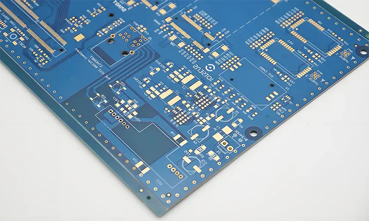
A brilliant circuit concept, meticulously planned on screen with every detail considered, only truly comes to life when transformed into a physical, functioning entity. This metamorphosis relies entirely on the skill, precision, and specialized knowledge applied during board fabrication and component assembly. When working with advanced substrates like Rogers RO3210, which possess unique material characteristics, the path from digital file to finished board demands more than standard manufacturing processes. It calls for dedicated Rogers RO3210 PCB Fabrication techniques and equally adept Rogers RO3210 PCB Assembly Services. Let’s explore the journey of bringing a Rogers RO3210 PCB into existence and how partnering with an experienced PCB Manufacturer like JarnisTech makes a tangible difference.
Mastering Rogers RO3210 PCB Fabrication Techniques
The creation of a bare Rogers RO3210 PCB from raw laminate involves several intricate stages demanding specialized handling and precise process control. Main fabrication considerations include:
| Fabrication Step | Technical Consideration | Key Parameters |
| Drilling | Prevent PTFE smearing, maintain hole quality | Drill speed: 20k–60k RPMChip load: 0.05–0.1 mm/rev |
| Routing/Machining | Prevent delamination and edge fraying | Use diamond-coated tools; slower feed rate |
| Hole Wall Preparation | Ensure copper adhesion in via barrels | Plasma or sodium etching treatment |
| Laminate Storage | Prevent moisture absorption | Store at <24°C, <50% RH in sealed packaging |
●Specialized Drilling & Machining: Adapting to the unique PTFE Ceramic Composite.
●Advanced Plating & Surface Finishing: Ensuring optimal adhesion and performance for RO3210 Circuit Board Fabrication.
●Strategic Sourcing & Partner Evaluation: Understanding how a dedicated partner enhances complex projects.
Specialized Drilling & Machining for PTFE Ceramic Composite
Drilling the PTFE Ceramic Composite that forms RO3210 requires a different approach than what’s used for conventional FR4. The PTFE content, being softer, can be prone to smearing if drilling parameters like speeds, feeds, and drill bit geometry are not optimized. Such smearing can obstruct proper via wall preparation for plating. Specialized drill bits and carefully controlled drilling protocols are employed to achieve clean, well-defined holes. Similarly, machining operations like routing and scoring must be adapted to the material to ensure smooth edges and accurate final dimensions for the RO3210 Circuit Board. At JarnisTech, our investment in specialized tooling and refined drilling protocols for materials like the PTFE Ceramic Composite ensures high precision and minimizes common fabrication issues.
Plating, Surface Finishes & RO3210 Circuit Board Fabrication
Achieving strong adhesion of copper plating to the PTFE-rich surfaces within drilled holes is a well-understood challenge in RO3210 Circuit Board Fabrication. This typically necessitates a specialized chemical surface preparation step, such as a sodium naphthenate etch, to modify the PTFE and create a receptive surface for the subsequent plating processes. Selecting an appropriate final surface finish – options often include ENIG (Electroless Nickel Immersion Gold), ENEPIG (Electroless Nickel Electroless Palladium Immersion Gold), or Immersion Silver – is also a consideration, based on the assembly requirements, operational environment, and the specific needs of the RF & Microwave PCB. Our expertise in surface preparation for RO3210 ensures robust copper adhesion, foundational for the long-term reliability of your RF & Microwave PCB.
Insights from a China PCB Manufacturer (BichengPCB RO3210)
When considering global sourcing options, such as exploring general China PCB Manufacturer offerings (with entities like BichengPCB RO3210 providing examples of available international services), it’s useful to weigh all factors. While various avenues exist, projects involving intricate Rogers RO3210 PCB Fabrication demand more than just capacity. They necessitate a partner deeply versed in the material’s subtleties. At JarnisTech, we provide that focused expertise. Unlike generalized production lines, our processes are specifically tuned for high-frequency materials, ensuring superior quality control, proactive technical communication, and a collaborative approach that ensures your nuanced requirements are not just understood, but meticulously executed, offering a level of dedicated support that makes a tangible difference in project outcomes.
Precision Rogers RO3210 PCB Assembly Services
Once the bare board is precisely fabricated, the next phase involves placing components onto the board, a process that demands specialized handling for Rogers RO3210 PCB Assembly Services. Focus areas include:
| Assembly Aspect | Critical Requirement | Recommended Practice |
| Reflow Profile | Thermal compatibility with RO3210’s expansion rate | Peak temp: ~245°C, ramp-up <3°C/sec, natural cooling |
| Solder Paste Type | Compatibility with ENIG/ENEPIG finishes | SAC305 for lead-free; Type 3 or 4 paste |
| Component Sourcing | High-frequency specific components | AVX, Murata, Mini-Circuits for RF parts |
| Placement Tolerance | Avoiding RF performance drift due to misalignment | ±50 µm for critical RF paths |
| PCB Support Fixtures | Prevent warpage during assembly | Use of ROHS-compatible carriers during reflow |
●SMT Process Management: Tailoring thermal profiles for RO3210’s unique properties.
●Specialized Component Sourcing: For high-frequency capacitors, inductors, and active devices used in RF & Microwave PCB assemblies.
●Expert Handling of Delicate Components: Ensuring the integrity of sensitive RF parts during PCB Assembly.
SMT & Component Sourcing for RF & Microwave PCB
Surface Mount Technology (SMT) is the predominant method for attaching components to modern PCBs. When assembling onto RO3210, the thermal profiles used in reflow soldering ovens must be carefully managed. RO3210 has different thermal expansion characteristics compared to standard FR4, and this needs to be accounted for to prevent undue stress on components or solder joints. Furthermore, RF & Microwave PCB assemblies often utilize specialized high-frequency capacitors, inductors, connectors, and active devices. Efficient and reliable component sourcing for these parts is a component of successful PCB Assembly.
The JarnisTech Advantage in PCB Assembly
At JarnisTech, our PCB Assembly workflows are specifically adapted for the demands of high-frequency boards built on substrates like Rogers RO3210. Our teams are experienced in handling delicate RF components, applying appropriate solder paste volumes, and utilizing precisely controlled reflow soldering profiles that respect the material’s thermal properties. For instance, our precise solder paste application and individually optimized reflow profiles for RO3210 minimize thermal stress, ensuring robust solder connections and preserving the integrity of both the board and the sensitive components it carries.
End-to-End Rogers RO3210 PCB Manufacturing Services
At JarnisTech, we provide a cohesive and comprehensive support structure for your high-frequency projects. Our End-to-End Rogers RO3210 PCB Manufacturing Services encompass:
●Collaborative Design Support (DFM): Optimizing your Rogers RO3210 PCB Design for manufacturability.
●Expert PCB Prototyping: For thorough design validation.
●Scalable Volume PCB Manufacturing: Meeting your production needs as they grow.
●Flexible Custom PCB & Quick Turn PCB Solutions: Adapting to unique requirements and development timelines.
Your One-Stop Shop: From Design Support to Production
Our End-to-End Rogers RO3210 PCB Manufacturing Services aim to streamline your project’s journey. This often begins with offering insights on Design for Manufacturability (DFM) related to your Rogers RO3210 PCB Design, helping to anticipate and mitigate potential fabrication challenges. Following this, we can facilitate PCB Prototyping for design validation, and then scale seamlessly to volume PCB Manufacturing as your needs grow. This integrated approach simplifies your supply chain and ensures high quality when you choose JarnisTech for your Rogers RO3210 projects.
Offering Custom PCB & Quick Turn PCB Solutions
Many high-frequency applications have unique and exacting requirements. We specialize in delivering Custom PCB solutions, working closely with you to ensure your specific needs are met. We also understand the pressures of modern development cycles and offer Quick Turn PCB services to support rapid iterations and help you bring your innovative products to market more swiftly.
Ensuring Quality: Testing & Reliability for RO3210 PCBs
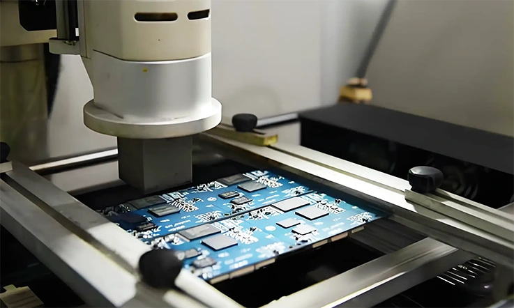
In applications where Rogers RO3210 substrates are chosen, the performance expectations are invariably high, and the dependability of the final electronic assembly is often a non-negotiable requirement. Quality, in this context, transcends a mere final check; it represents a philosophy woven throughout the entire manufacturing sequence. Delivering a High Reliability PCB is the culmination of meticulous processes, comprehensive verification steps, and a deep-seated commitment to excellence.
For organizations involved in Military Equipment Manufacturing or creating devices for Medical Device OEM markets, these assurances are fundamental. Let’s explore the measures undertaken to confirm that every RO3210 Circuit Board meets these exacting standards – standards that JarnisTech rigorously upholds in every Rogers RO3210 project we undertake.
Rigorous Quality Assurance Protocols
A robust approach to quality assurance (QA) is integral to our operations at Jarnistech. This involves multiple layers of scrutiny designed to identify and address potential deviations throughout the production cycle, including:
●Continuous In-Process Monitoring: From material reception to final fabrication stages.
●Comprehensive Final Inspection Methodologies: Utilizing advanced tools like AOI and X-Ray.
●Adherence to Stringent Quality Standards: Meeting and often exceeding industry best practices for High Reliability PCB.
In-Process & Final Inspection (AOI, X-Ray)
The pursuit of quality is not deferred until the end of the line; it begins with the very first steps of PCB Fabrication and continues diligently. In-process inspections monitor stages like etching accuracy, drilling precision, and plating uniformity. Before any board is cleared for shipment, it undergoes a thorough final visual and dimensional assessment. This frequently incorporates Automated Optical Inspection (AOI) systems. These sophisticated machines use high-resolution cameras to scan each board, comparing it against the original layout data to detect subtle variations such as incorrect trace widths, spacing anomalies, potential shorts, or other physical defects.
For complex multi-layer boards or assemblies featuring components with hidden connections (like Ball Grid Arrays – BGAs), X-Ray Testing provides an invaluable window. This allows for the inspection of internal layers, via integrity, and solder joint quality beneath components, ensuring the internal structure of the RO3210 Circuit Board is sound. At Jarnistech, we employ these advanced inspection techniques on Rogers RO3210 PCBs to provide our clients with the highest confidence in the structural integrity and precision of their boards.
Comprehensive Electrical & Performance Testing
Visual and structural inspections are foundational, but verifying a board’s electrical performance is equally substantial. At Jarnistech, our comprehensive electrical testing for RO3210 Circuit Boards includes:
●Bare-Board Electrical Integrity Checks: Identifying shorts or opens pre-assembly.
●Post-Assembly Functional Verification: Confirming overall circuit operation.
●Specialized High-Frequency Performance Measurements: Validating performance for RF & Microwave PCB applications.
Verifying High Frequency Circuit Board Performance
Electrical testing often starts with the bare board, even before components are mounted. Techniques such as flying probe testing or bed-of-nails fixtures are used to check for electrical shorts between traces that shouldn’t be connected, and opens in pathways that should be continuous. Identifying such issues at this early stage prevents the population of faulty boards, saving time and resources. Following component assembly, functional testing is conducted to confirm that the entire populated circuit operates according to its specifications.
For a High Frequency Circuit Board built using materials like RO3210, specialized test equipment comes into play. Network analyzers, for example, are often employed to measure S-parameters – like insertion loss (how much signal is lost through the board) and return loss (how much signal is reflected) – and to verify characteristic impedance. Our testing protocols at Jarnistech, utilizing equipment like network analyzers, are designed to provide concrete verification that your Rogers RO3210 based RF & Microwave PCB performs precisely as intended.
Environmental & Stress Testing for Mission-Critical Use
For applications where the final product will operate in challenging environments or where unwavering reliability is an absolute pre-condition, boards may undergo specific environmental stress screening (ESS). These tests are designed to accelerate potential failure mechanisms and reveal any latent weaknesses that might not appear under benign conditions. Common procedures include thermal cycling, where boards are subjected to repeated transitions between temperature extremes, simulating years of operational temperature swings. Vibration testing can assess the mechanical resilience of the board and its solder joints. Humidity testing evaluates performance in damp conditions. Such rigorous evaluations are frequently part of the validation for High Reliability PCB destined for demanding fields.
While JarnisTech can facilitate and manage specific Environmental Stress Screening (ESS) requirements through certified partners, our core manufacturing philosophy for Rogers RO3210 is to build boards inherently designed and fabricated to withstand such conditions. Our meticulous material selection, process controls during PCB manufacturing and assembly, and stringent in-house testing contribute to producing RO3210 PCBs that have a higher likelihood of successfully passing these demanding validations. We are committed to delivering products that provide an exceptional layer of assurance for long-term dependability in your most applications, including those for Medical Device OEM markets and Military Equipment Manufacturing.
Rogers RO3210 PCB: Frequently Asked Questions
1.Q: Which prepregs or bondply materials are compatible with RO3210 for multilayer PCBs?
A: Rogers offers compatible options like their RO4400™ series or 2929 bondply for RO3210 multilayer constructions.
2.Q: Does RO3210 material exhibit significant outgassing in vacuum environments?
A: Yes, RO3210 typically demonstrates low outgassing characteristics, suiting it for vacuum and aerospace applications.
3.Q: What are the standard copper foil weights available for RO3210 laminates?
A: Common copper foil weights for RO3210 include ½ oz (17 µm) and 1 oz (35 µm); other weights like 2 oz (70 µm) may also be available.
4.Q: Is RO3210 primarily available in a specific color?
A: Rogers RO3210 laminates are typically off-white or a light tan, reflecting their PTFE and ceramic composition.
5.Q: What level of moisture absorption does RO3210 typically exhibit?
A: RO3210 shows very low moisture absorption (typically under 0.10%), contributing to stable electrical properties in varied humidity.
Our services
Rogers PCB Laminates & Series


