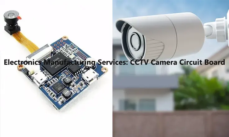
CCTV cameras have become an essential tool for surveillance and security in various settings, including homes, businesses, and public spaces. At the heart of every CCTV camera is a circuit board that contains the electronic components responsible for capturing and processing video signals. The design and manufacturing of CCTV camera circuit boards require careful consideration of various factors, including image sensor selection, power supply, signal integrity, thermal management, and quality control. In this article, we will explore definition, Design, Manufacturing, materials, types, and the importance of CCTV camera circuit board technology and the potential future developments in this field.
What Is A CCTV PCB ?
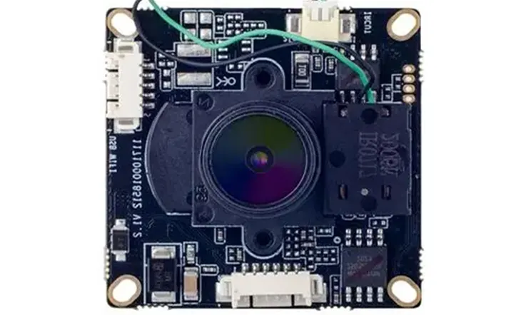
A CCTV PCB board is a compact video recording device integrated onto a printed circuit board, widely known for its versatility. By directly incorporating optical and sensor components into the circuit board, manufacturers can achieve a more streamlined design by eliminating the need for external components. These PCB boards are commonly employed in workplace surveillance systems.
A CCTV camera PCB functions as a digital camera, with the aperture, lens, and image sensor interconnected to the board using standard input and output connections. This allows for a compact form factor, typically featuring a 1/3″ overall lens diameter.
While CCD sensors are frequently utilized, CMOS and CID sensors are also available. CCTV PCB boards maintain the essential functionality of surveillance cameras, even in the absence of specific features.
Components of a CCTV Camera Circuit Board
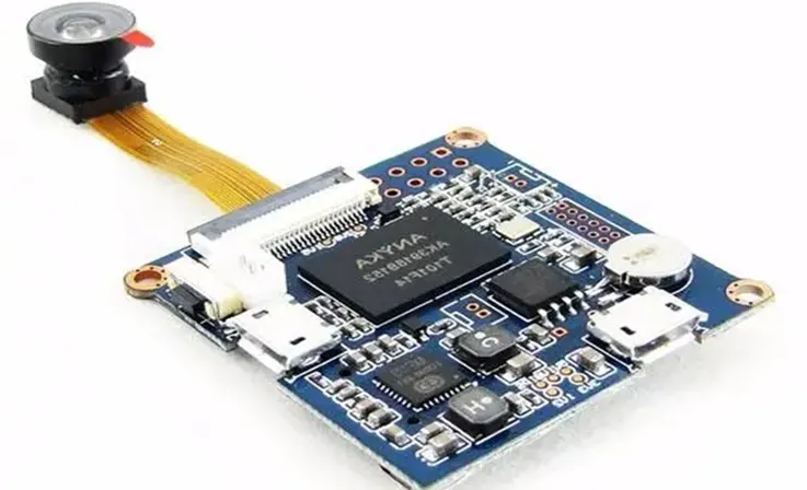
A CCTV camera circuit board is a complex electronic system that includes multiple components. Some of the common components found in a CCTV camera circuit board include:
Image Sensor: The image sensor is the most important component of a CCTV camera circuit board. It captures the light that enters the lens and converts it into an electrical signal.
Lens: The lens is responsible for focusing the light onto the image sensor. It determines the field of view and the level of magnification of the camera.
Processor: The processor is the brain of the CCTV camera circuit board. It processes the images captured by the image sensor and converts them into a digital format.
Memory: The memory component stores the digital images and video captured by the camera. It can be either volatile (RAM) or non-volatile (ROM or Flash memory).
Power Supply: The power supply component provides power to the camera circuit board. It can be either a battery or a power adapter.
Video Encoder: The video encoder converts the digital signal from the processor into a format that can be transmitted over a network or stored on a digital video recorder (DVR).
Connectors: Connectors are used to connect the various components of the CCTV camera circuit board. They include interfaces for the power supply, data transfer, and control signals.
PCB and other supporting components: Printed Circuit Board (PCB) is the backbone of the CCTV camera circuit board, which connects all the components together. Other supporting components such as resistors, capacitors, transistors, diodes, and ICs are also used to ensure proper functioning of the circuit board.
Types of CCTV Camera Circuit Boards
There are various types of CCTV camera circuit boards available in the market. Some of the most common types include:
Analog CCTV Camera Circuit Board: This type of circuit board is used in traditional analog CCTV cameras. It converts the analog signal from the camera into a digital signal to be transmitted over a coaxial cable.
IP CCTV Camera Circuit Board: This type of circuit board is used in IP cameras and is designed to convert the analog signal into a digital signal that can be transmitted over a network.
HD CCTV Camera Circuit Board: This type of circuit board is designed to support high-definition video, typically 720p or 1080p resolution. It can be used in both analog and digital CCTV cameras.
Wireless CCTV Camera Circuit Board: This type of circuit board is designed to support wireless data transmission, allowing the camera to transmit video over a Wi-Fi or cellular network.
PTZ CCTV Camera Circuit Board: This type of circuit board is used in pan-tilt-zoom cameras and includes additional circuitry to control the movement of the camera.
Thermal CCTV Camera Circuit Board: This type of circuit board is designed to support thermal imaging cameras, which use infrared radiation to detect heat signatures.
Day/Night CCTV Camera Circuit Board: This type of circuit board is designed to support cameras that can switch between color and black-and-white modes depending on the lighting conditions.
Dome CCTV Camera Circuit Board: This type of circuit board is used in dome cameras, which are designed to be discreet and blend in with the surrounding environment.
Circuit Board Design Considerations for CCTV Cameras
Designing a circuit board for CCTV cameras requires careful consideration of several factors to ensure optimal performance and reliability. Some of the key design considerations for CCTV camera circuit boards include:
Image Sensor Selection: The selection of an appropriate image sensor is critical for the performance of the CCTV camera. The image sensor should be able to capture high-quality images in low light conditions and have a suitable resolution for the camera’s intended use.
Power Supply: The power supply should be designed to provide stable and reliable power to the camera circuit board. It should also be able to handle the power requirements of the various components on the board.
Signal Integrity: The design should ensure that the signals between different components on the board are transmitted with minimal interference and distortion. This can be achieved by careful routing of the traces on the PCB and by using appropriate shielding.
Thermal Management: CCTV cameras generate heat, which can affect the performance and lifespan of the components. The circuit board design should include adequate thermal management measures, such as heatsinks and thermal vias, to dissipate heat and maintain a stable operating temperature.
EMC/EMI Considerations: CCTV cameras can be sensitive to electromagnetic interference (EMI) and can also generate electromagnetic emissions (EMC). The circuit board design should include measures to minimize EMI and ensure compliance with relevant EMC standards.
Form Factor: The form factor of the circuit board should be designed to fit the intended camera housing or enclosure. This may involve designing the board to be compact and space-efficient, with a suitable arrangement of components and connectors.
Manufacturing and Assembly Considerations: The circuit board design should take into account the manufacturing and assembly processes, including the placement of components, trace routing, and testing procedures.
By considering these factors in the circuit board design, the resulting CCTV camera will be of high quality and reliability.
Manufacturing process of CCTV camera circuit boards
The manufacturing process for CCTV camera circuit boards involves several steps that are similar to those used in the production of other electronic devices. The following are the typical steps involved in the manufacturing process of CCTV camera circuit boards:
Design and Prototyping: The first step in the process involves creating a design for the CCTV camera circuit board and prototyping it. The design is typically done using software tools such as Computer-Aided Design (CAD) software. Once the design is finalized, a prototype is created to test the functionality and design of the circuit board.
Component Sourcing: Once the prototype is approved, the next step is to source the components needed for the circuit board. This involves identifying the required components, selecting suppliers, and placing orders.
PCB Fabrication: The circuit board is created by printing the circuit design onto a PCB using a photoresist process. The PCB is then drilled and plated to create the required connections between components.
Component Placement: Once the PCB is ready, the components are placed on the board using a pick and place machine. The machine uses computer-controlled arms to place the components accurately and quickly.
Soldering: The components are then soldered onto the PCB using a wave soldering or reflow soldering process. This ensures that the components are firmly attached to the board and the connections are strong.
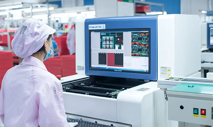
Testing: The completed circuit board is then tested to ensure that it functions correctly. This involves checking the connections, testing the power supply, and verifying the functionality of each component.
Assembly: Once the circuit board is tested and approved, it is assembled into the camera housing or enclosure. This involves connecting the circuit board to the other camera components, such as the lens and power supply.
Final Testing: The completed CCTV camera is then tested to ensure that it meets the required specifications and standards. This includes testing the image quality, power consumption, and operational stability of the camera.
Quality Control: Finally, the CCTV camera is subjected to quality control checks to ensure that it meets the required quality standards. This includes checks for reliability, durability, and compliance with relevant regulations and standards.
By following these steps, manufacturers can create high-quality CCTV camera circuit boards that are reliable and functional.
What Are the Materials of CCTV PCB ?
A CCTV PCB consists of two primary components, namely the circuit board and the camera module. The circuit board is responsible for providing the electrical connections and components necessary for the device to function. It is typically manufactured using a range of materials, including but not limited to:
PCB Materials
The most widely used substrate material for PCBs is fiberglass epoxy resin, which features copper foil adhered to one or both sides. In cost-effective electronic devices, PCBs made of paper-reinforced epoxy resins with bonded copper foil are commonly employed.
Copper is utilized in the construction of printed circuits, either by coating or etching it away from the substrate surface to achieve the desired circuitry pattern.
To safeguard copper circuits from oxidation, they are coated with a layer of tin-lead. The contact fingers undergo a series of coatings, starting with tin-lead, followed by nickel, and ultimately gold, ensuring optimal conductivity.
When it comes to components, capacitors, resistors, transistors, electronic circuit chips, diodes, and other electronic elements are procured for integration into the PCB assembly.
Camera Materials
Glass is extensively utilized as a lens element material due to its optical properties and scratch resistance. Additional materials employed in lens construction include quartz glass, fluorite, acrylic (Plexiglass), germanium, and meteoritic glass.
Plastics offer the advantage of producing highly aspherical lens elements, a task that is challenging or unachievable with glass. However, plastics are generally limited to inexpensive lenses due to their susceptibility to scratches.
Molded plastic optics have historically been utilized in low-cost disposable cameras, which has garnered criticism from optical experts who prefer to use terms like “optical resin” to describe them.
In contemporary high-performance and expensive lenses, aspherical elements are frequently molded using plastics. Therefore, it is incorrect to assume that cameras incorporating plastic components are inherently of poor quality.
Features of CCTV Camera Circuit Board
CCTV PCBs are employed for their compact design and durable nature, offering distinct advantages over other types of PCBs. The key distinguishing features of CCTV PCBs include:
Video Output
The majority of PCB cameras offer a video feed through a 75-ohm composite output. However, alternative options are available as well. In certain cases, PCB cameras can transmit wireless signals using a basic power supply. USB and Firewire connectivity is typically available when a memory is connected to the camera circuit board, enabling convenient data transfer and storage options.
Sensitivity
The sensitivity of PCB cameras in low-light situations is commonly quantified in lux units. Monochrome PCB cameras exhibit higher sensitivity compared to their color counterparts, and certain monochrome cameras are capable of capturing images even in conditions as dim as .0003 lux. This capability proves beneficial in the design of spy camera circuit boards. On the other hand, colored PCB cameras require more illumination to capture high-quality images. Premier color PCB cameras typically have a minimum lux level of .3 lux to ensure optimal performance.
Shutter Speed/Exposure
PCB cameras employ a sophisticated image sensor instead of a traditional viewfinder, providing a visual representation of the scene. These cameras utilize an electronic shutter mechanism to ensure that the image sensor captures a well-balanced image. In the case of pinhole cameras, a fixed exposure rate is predetermined due to the inability to adjust the aperture. PCB cameras commonly incorporate auto-exposure functionality, allowing for automatic adjustment of exposure settings based on the prevailing lighting conditions.
Frame Rate
Camera PCBs typically operate at a frame rate of approximately 30 frames per second, which is the standard frame rate for television broadcasting. Due to the compact nature of PCB cameras and the trade-offs made to accommodate their small form factor, devices capable of recording at frame rates exceeding 100 frames per second are considered high speed. These higher frame rates are generally unnecessary for PCB cameras since they are not typically used for motion analysis or tracking. Therefore, the standard frame rate of 30 frames per second is typically more than sufficient for their intended applications.
Resolution
Compared to larger cameras, PCB cameras generally have lower resolution capabilities. An excellent resolution for PCB cameras is often around 700 TVL (Television Lines). However, even reasonably priced PCB cameras typically offer resolutions ranging from 380 to 480 TVL.
Testing and Quality Control for CCTV Camera Circuit Boards
Testing and quality control are critical steps in the manufacturing process of CCTV camera circuit boards. Here are some common testing and quality control procedures for CCTV camera circuit boards:
Electrical Testing: Electrical testing involves checking the functionality of the circuit board components, such as the image sensor, processor, memory, and power supply. This is typically done using automated testing equipment that can detect faults in the circuit board.
Image Quality Testing: Image quality testing involves assessing the quality of the images captured by the CCTV camera. This is typically done using a test chart or scene that can be used to evaluate the resolution, color accuracy, and other image quality parameters.
Environmental Testing: Environmental testing involves subjecting the CCTV camera to various environmental conditions, such as temperature, humidity, and vibration. This is done to ensure that the camera can operate reliably in different environments and conditions.
EMC/EMI Testing: EMC/EMI testing involves testing the CCTV camera circuit board for compliance with electromagnetic compatibility (EMC) and electromagnetic interference (EMI) standards. This is done to ensure that the camera can operate reliably in the presence of electromagnetic radiation and can avoid causing interference with other devices.
Reliability Testing: Reliability testing involves subjecting the CCTV camera to long-term use and testing to ensure that it can operate reliably over its expected lifespan. This is typically done using accelerated life testing methods that simulate the expected use conditions of the camera.
Quality Control: Quality control involves ensuring that the CCTV camera circuit board meets the required quality standards. This involves checking for defects, ensuring compliance with relevant regulations and standards, and verifying that the camera meets the required specifications.
By performing these testing and quality control procedures, manufacturers can ensure that the CCTV camera circuit board is of high quality, reliable, and meets the required performance and safety standards.
Considering Factors before Choosing A CCTV Camera Circuit Board
When making a decision about the appropriate CCTV PCB (Printed Circuit Board) for your surveillance system, careful consideration of several factors is crucial.
● Firstly, prioritize compatibility by selecting a CCTV camera PCB board specifically designed for your camera model.
● Additionally, assess the quality of the PCB, taking into account the materials used and adherence to manufacturing standards. Opting for a reliable and durable PCB is vital to ensure consistent and long-lasting performance.
● Furthermore, evaluate the supported features and functionality offered by the PCB, such as resolution, video signal processing, and supplementary capabilities like audio or motion detection.
● Lastly, consider the cost-effectiveness of the PCB and the availability of technical support from the manufacturer, as these elements contribute to a well-informed decision when choosing a CCTV camera PCB board that meets your surveillance requirements.
Troubleshooting Common Issues with CCTV Camera Circuit Boards
CCTV cameras can experience a range of issues with their circuit boards, which can affect their performance and reliability. Here are some common issues with CCTV camera circuit boards and possible troubleshooting solutions:
No Power: If the CCTV camera is not powering on, it may be due to a faulty power supply or a connection issue. Check the power supply and connections to ensure they are properly connected and functioning.
Poor Image Quality: Poor image quality may be due to a faulty image sensor, lens, or image processing circuitry. Check and replace the faulty component as needed.
No Signal: If the CCTV camera is not transmitting a signal, it may be due to a faulty video encoder or a connection issue. Check the video encoder and connections to ensure they are properly connected and functioning.
Overheating: Overheating can cause the CCTV camera to malfunction or shut down. Ensure that the thermal management measures on the circuit board are functioning correctly.
Intermittent Issues: If the CCTV camera is experiencing intermittent issues, it may be due to a loose connection or a faulty component. Check and replace the faulty component or tighten any loose connections as needed.
Noise or Distortion: Noise or distortion in the image signal may be due to electromagnetic interference (EMI) or a faulty component. Check for EMI sources, such as nearby electrical equipment, and replace any faulty components.
Camera Movement Issues: If the CCTV camera is not moving as intended, it may be due to a faulty pan-tilt-zoom (PTZ) circuitry or motor. Check and replace the faulty component as needed.
Network Connectivity Issues: If the CCTV camera is not connecting to the network, it may be due to a faulty network interface or configuration issue. Check and replace the faulty component or reconfigure the network settings as needed.
In general, troubleshooting CCTV camera circuit board issues involves identifying the faulty component or connection and replacing or repairing it as needed. It is also important to ensure that the CCTV camera is properly maintained and that the circuit board is protected from environmental factors that can affect its performance.
Future Developments in CCTV Camera Circuit Board Technology
The field of CCTV camera circuit board technology is constantly evolving, with new developments and innovations being introduced to improve the performance and functionality of CCTV cameras. Here are some potential future developments in CCTV camera circuit board technology:
Artificial Intelligence (AI) Integration: AI technology is being increasingly integrated into CCTV cameras, allowing for advanced features such as facial recognition, object detection, and behavior analysis.
Edge Computing: Edge computing involves processing data at the edge of the network, closer to the source of the data. This technology can improve the performance and reliability of CCTV cameras by enabling faster processing and reducing network latency.
Higher Resolution Image Sensors: Higher resolution image sensors can provide greater detail and clarity in CCTV camera images, allowing for better identification and analysis of objects and people.
Enhanced Low-Light Performance: Low-light performance is a critical factor for CCTV cameras, particularly those used in outdoor or low-light environments. Future developments in image sensor technology and image processing circuitry may improve low-light performance.
Increased Integration with IoT Devices: CCTV cameras may become increasingly integrated with other IoT devices, such as smart home devices, to provide enhanced functionality and convenience.
Wireless Power Transmission: Wireless power transmission technology may eliminate the need for power cables and allow for more flexible placement of CCTV cameras.
Enhanced Security Features: Future developments in security features, such as encryption and authentication, may improve the security of CCTV camera systems.
Overall, future developments in CCTV camera circuit board technology are likely to focus on improving performance, functionality, and convenience while ensuring the security and reliability of the camera systems.
Conclusion and Final Thoughts
In conclusion, CCTV camera circuit board technology plays a critical role in the performance, functionality, and reliability of CCTV camera systems. The design and manufacturing of CCTV camera circuit boards require careful consideration of various factors, including image sensor selection, power supply, signal integrity, thermal management, and quality control. Troubleshooting and testing procedures are also critical to ensure that the CCTV camera circuit board functions as intended.
Developments in AI integration, edge computing, higher resolution image sensors, low-light performance, IoT integration, wireless power transmission, and enhanced security features are likely to shape the evolution of CCTV camera circuit board technology.
We hope that this information has been informative and helpful in understanding the importance of CCTV camera circuit board technology and the potential future developments in this field. As technology continues to evolve, it is important to stay informed and up-to-date on the latest trends and innovations in CCTV camera circuit board technology.