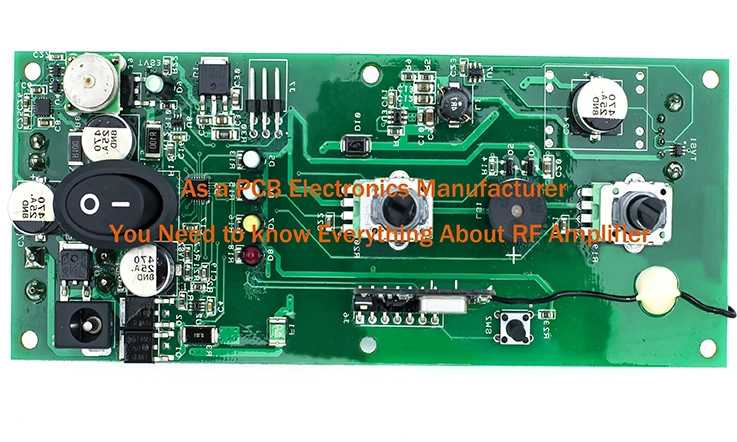
Radio Frequency (RF) amplifiers play a role in modern communication systems by boosting radio frequency signals for wireless communication over long distances. They are commonly used in devices like cell phones Wi Fi routers, radar systems and scientific research tools.
When designing RF amplifiers engineers need to consider factors such as gain, bandwidth, efficiency, stability, distortion, noise levels, impedance matching, power handling capacity, linearity and heat management. Impedance matching is particularly vital in RF amplifier design to ensure power transfer and minimize signal reflections.
Power amplifiers are a type of RF amplifier with unique requirements like high output power capability, efficiency, linearity, stability across frequencies, broad operational range capabilities, strong power handling abilities, low noise output levels and built in protection mechanisms.
To streamline the design process for RF amplifiers and meet these requirements effectively; designers can leverage to use RF amplifier modules and integrated circuits (ICs). These components offer benefits such, as design cycles reduced assembly complexity enhanced reliability and cost savings. However; it’s essential for designers to thoroughly assess the performance compatibility and cost implications of these components before integration.
What Is a Radio Frequency (RF) Amplifier ?
A radio frequency (RF) amplifier plays a role in boosting the power of a radio signal by transforming a weaker signal into a stronger one, for sending or receiving. These gadgets are designed to enhance signals within a set frequency range thus improving the amplification procedure.
Transistors are fundamental components within a radio frequency amplifier that play a crucial role in amplifying signal power. These solid-state devices serve as electrical switches or relays, with the ability to handle much higher power levels than the incoming signal. When activated by a low-power signal, a transistor closes two connections, resulting in an amplified output. Unlike conventional switches, transistors can be quickly toggled and only require an electrical signal to establish a connection.
In a radio frequency amplifier transistors can be turned on and off in sync with the radio signal being boosted. This technique duplicates the signal at a higher power by swiftly switching transistors much like quickly turning on a bright lamp in response to a faint Morse code message. Nonetheless the rapid switching pace of transistors, in a radio frequency amplifier exceeds abilities with numerous amplifiers capable of toggling signals thousands or even millions of times every second.
Common Types of RF Amplifiers
These RF Amplifiers have advantages and disadvantages. In the conversation we’ll delve into various kinds of these amplifiers to grasp their unique qualities.
Class A Amplifiers: Class A amplifiers are characterized as the most basic type of RF amplifiers, functioning in the linear region through transistor biasing. While they offer excellent linearity and minimal distortion, their efficiency is relatively low.
Class B Amplifiers: These amplifiers are created using a dual transistor push pull setup, where each transistor handles a part of the input signal waveform. While they are praised for their improved efficiency compared to Class A amplifiers there is a chance they may show levels of distortion.
Class AB Amplifiers: Class AB amplifiers incorporate elements from both Class A and Class B amplifier designs, employing two transistors similar to Class B configurations. The biasing is specifically adjusted to ensure that the transistors remain slightly conducting even in the absence of an input signal, a feature intended to reduce distortion levels while simultaneously optimizing efficiency.
Class C Amplifiers: Utilizing a highly nonlinear transistor that conducts only during a small segment of the input signal waveform, Class C amplifiers are known for their high efficiency. However, they exhibit significant distortion and are not recommended for applications that necessitate superior linearity.
Class D Amplifiers: Employing a switching transistor that operates in a binary manner, either fully ON or fully OFF without a linear mode, Class D amplifiers are recognized for their exceptional efficiency. However, they are susceptible to high distortion levels and necessitate the incorporation of a low-pass filter to mitigate switching noise.
Class E Amplifiers: Class E amplifiers, akin to Class D amplifiers, make use of resonant circuits to reduce switching losses and boost efficiency. Their application is prevalent in high-frequency settings owing to their exceptional performance attributes.
Class F Amplifiers: These amplifiers employ resonant circuits to manipulate the output waveform and minimize switching losses. While highly efficient, they necessitate meticulous tuning and exhibit greater complexity compared to other amplifier variants.
Every RF amplifier type offers distinct advantages and limitations, with the selection of the appropriate amplifier contingent upon the specific needs of the application at hand.
Applications of RF Amplifiers
RF (Radio Frequency) amplifiers find utility across a diverse spectrum of applications necessitating the amplification of radio frequency signals. Herein lie some prevalent applications of RF amplifiers:
●Wireless communications
●Broadcast
●Radar
●Industrial heating
●Medical equipment
●Scientific research
●Military and defense
●Automotive
RF amplifiers find utility across a spectrum of applications necessitating amplification of radio frequency signals, with the selection of amplifier design and class hinging on the unique demands of the particular application at hand.
Design Considerations for RF Amplifiers
Creating an RF (Radio Frequency) amplifier involves taking into account factors to achieve optimal performance. When designing RF amplifiers it is essential to consider the following aspects:
Frequency Coverage: An amplifiers frequency range should be flexible and suitable, for a range of devices and uses. Typically the frequency range falls between 500 MHz and 5 GHz.
Gain: The suitable gain for an amplifier is contingent upon its specific application, although a generally accepted range falls between 10 to 20 dB. An amplifier with a broad frequency range is preferred for achieving this gain. Ideally, the amplifier should exhibit a consistent gain over a span of approximately 100 MHz, with attenuation levels below 0.2 dB.
Input/output impedance: As stated earlier, the impedance for both the input and output is configured at 50 ohms.
Noise figure: As the operational frequency of a device increases, the corresponding elevation in noise levels poses a substantial challenge to amplifier effectiveness. Hence, meticulous attention must be directed towards the noise figure of the amplifier. Ensuring the maintenance of a consistent signal-to-noise ratio, typically quantified in decibels (dB), between the amplifier’s input and output is paramount. Ideally, the discrepancy in ratios should not surpass 2 dB, although values below 3 dB are commonly accepted in practical scenarios.
Output Power: When operating with a 50-ohm load and the supply voltage at its maximum, the maximum attainable level should be considered. The output power is typically measured in dBm and should fall within the ideal range of 12 to 28 dBm.
Third-order intercept and 1-dB compression points: The efficiency of the power-boosting amplifier can be gauged by several factors. Typically, devices utilize a broadband modulation scheme while maintaining a decent level of linearity. This approach ensures optimal data retention and maximizes broadband utilization.
Solid-state technology: When high-frequency devices are utilized, CMOS silicon can be used for amplifier construction. Nonetheless, it is more prevalent to fabricate amplifiers from gallium arsenide or silicon germanium, with the latter being marginally more dependable than the former. These compounds demonstrate enhanced performance compared to standard silicon when operating at high frequencies.
DC Power: Most RF amplifiers operate within a voltage range of 1.8 to 6 V, while the current channels required for optimal device performance are contingent upon the level and type of power generated, ranging from 20 to 100 mA. It is imperative that the amplifier includes a standby mode that maintains a minimum current level to ensure continuous device operation.
Packaging: The packaging dimensions are compact, typically falling within the range of 4 to 25 square millimeters.
Temperature: The acceptable temperature range falls within the limits of negative forty degrees Celsius and positive one hundred and five degrees Celsius.
The particular design considerations will vary based on the application’s requirements, necessitating the optimization of the amplifier design to fulfill these requirements while carefully managing the trade-offs involved.
Matching Networks and Impedance Matching
In creating RF (Radio Frequency) amplifiers it’s crucial to think about matching networks and impedance matching. Impedance matching involves aligning the input and output impedances of the amplifier with the source and load impedances to optimize power transfer and reduce reflections. A matching network serves as a circuit utilized to attain impedance matching.
Please find the following are some key points to consider when designing matching networks and performing impedance matching:
Input impedance matching: The attainment of alignment between the input impedance of the amplifier and the source impedance holds significant importance in reducing reflections and enhancing power transfer efficiency. To accomplish this, a matching network is commonly employed at the input of the amplifier.
Output impedance matching: Matching the output impedance of the amplifier to the load impedance is crucial to reduce reflections and optimize power transfer. Usually a matching network positioned at the amplifiers output is employed to accomplish this.
Transmission line matching: If the source and load are connected by a transmission line, the characteristic impedance of the transmission line must also be matched to the source and load impedances to avoid reflections.
Matching network design: The design of the matching network depends on the specific requirements of the application and the input and output impedances of the amplifier. Common matching network topologies include pi-networks, T-networks, and L-networks.
Impedance matching components: The components used in the matching network should have low loss and high Q to minimize signal attenuation and distortion. Common components include capacitors, inductors, and transmission line sections.
Broadband matching: Some applications require broadband impedance matching over a wide range of frequencies. This can be achieved using a combination of broadband components and matching network topologies.
Passive vs. active matching: In the realm of impedance matching, designers have the choice between utilizing passive components such as capacitors and inductors, or active components like transformers and amplifiers. While active matching can offer performance in certain scenarios it does introduce more intricacy and expenses into the amplifiers design.
Impedance matching plays a role, in RF amplifier design with a carefully crafted matching network enhancing amplifier performance by optimizing power transfer and reducing reflections.
Power Amplifiers and Their Requirements
Power amplifiers represent a distinct category of RF (Radio Frequency) amplifiers meticulously engineered to provide substantial power output for driving loads, including antennas and transmission lines. please find the following some requirements that are specific to power amplifiers:
High output power: Power amplifiers have to be able to provide output high power to operate the load effectively. The necessary output power varies depending on the use case ranging anywhere, from a few watts to kilowatts.
High efficiency: As we know, Power amplifiers have to be designed to operate efficiently, minimizing power dissipation to avoid overheating and to maximize battery life in portable applications. Efficiency is attained by employing amplifier designs, like Class D, E and F.
Linearity: Maintaining excellent linearity is a critical requirement for power amplifiers to uphold signal integrity and deliver superior-quality output signals, devoid of distortion. Achieving this objective involves employing linear amplifier topologies, such as Class A and AB, renowned for their inherent linearity characteristics. Alternatively, linearity can be enhanced by implementing advanced techniques such as predistortion, which effectively mitigates distortion effects and ensures optimal signal linearity.
Stability: Power amplifiers must be designed to be stable over the range of operating conditions, including variations in load impedance and temperature. Stability can be achieved by using feedback circuits and by modeling and simulating the amplifier behavior under different conditions.
Broadband operation: Power amplifiers must be designed to operate over a wide range of frequencies to accommodate different applications. Broadband operation can be achieved by using wideband matching networks and by using amplifier topologies that are inherently broadband, such as Class E and F.
High power handling capability: Why Power amplifiers must be designed to handle the high power levels required by the application without damage or degradation? Cos it need requires the use of high-quality components that can withstand high power levels and careful thermal management to dissipate the heat generated by the amplifier.
Low noise: Power amplifiers must provide low noise output to avoid adding noise to the output signal. Therefore, Achieved through the implementation of low-noise amplifier topologies and the meticulous reduction of noise sources within the amplifier. By employing these measures, power amplifiers can effectively maintain a low noise output, thereby preventing the introduction of undesirable noise into the amplified signal.
Protection circuits: To prevent harm to the amplifier and the load during situations of voltage, excessive current or unusual scenarios it is crucial to incorporate protective mechanisms in power amplifiers. These safety features play a role, in quickly identifying and addressing these conditions ensuring the durability and performance of both the amplifier and the load.
The specific requirements of a power amplifier depend on the application, and the amplifier design must be optimized to meet these requirements while balancing the various trade-offs.
RF Amplifier Modules and Integrated Circuits
RF amplifier modules and integrated circuits (ICs) are standardized components that offer pre-designed and pre-manufactured solutions, contributing to the streamlined process of RF amplifier design. Thefore, when utilizing RF amplifier modules and ICs, please find the following some essential factors to contemplate:
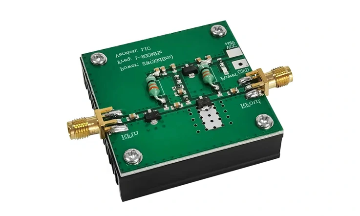
Advantages: RF amplifier modules and ICs have benefits compared to individual component designs. These advantages include saving time in design making assembly easier enhancing reliability and lowering costs.
Types of modules and ICs: A variety of RF amplifier modules and integrated circuits are accessible in types and setups providing a wide selection to meet diverse application demands. These options encompass power amplifiers, low noise amplifiers, driver amplifiers and variable gain amplifiers.
Application-specific modules and ICs: Certain manufacturers specialize in crafting RF amplifier modules and ICs that are tailored specifically for applications such as cellular communications, GPS and Wi Fi. These customized products are designed to ensure performance and compatibility, within their designated fields addressing the specific needs of each application.
Evaluation kits: Many RF amplifier module and IC manufacturers offer evaluation kits that allow designers to test and evaluate the performance of the component in their specific application before committing to a design.
Design considerations: It is imperative for design engineers to thoroughly assess the compatibility between RF amplifier modules and ICs and the remaining components within the amplifier circuit. all in all, it is crucial to ascertain that the performance of these components aligns with the specific requirements of the application at hand. Morever, an evaluation may mandate the incorporation of supplementary matching circuitry or other essential modifications to the overall amplifier design.
Cost considerations: RF amplifier modules and ICs can streamline the design process; They may introduce additional expenses to the end product. So, Designers must balance the benefits of using pre-manufactured components with the cost of the components and any modifications required to the amplifier design.
Availability: RF amplifier modules and ICs may have limited availability or long lead times, especially for specialized applications or custom designs.
Summary
RF (Radio Frequency) amplifiers contribute remarkably in escalating radio frequency signals in diverse domains such as wireless communications, broadcasting, radar systems, medical appliances, and scientific research. When tasked with engineering RF amplifiers, consideration must be given to factors that include amplification intensities, frequency diversity, efficiency, reliability, interference reduction, signal quality, and crucially, impedance alterations – all of which impact the performance. It is paramount that extraordinary emphasis is placed on impedance matching – a feat attainable through the utilization of matching networks to reconcile the input and output impedances of the amplifier with those originating from the source and extending to the destination.
The design of RF amplifiers necessitates meticulous attention to a broad spectrum of considerations, with the specific requirements contingent upon the intended application. By comprehensively understanding these critical elements, designers can enhance the performance of their RF amplifier designs and achieve consistent and high-fidelity output signals.
Related Posts:
1.Guide to RF PCB Design and Microwave Material Selection
3.RF Multiplexer: Design, Types, Functions and Applications
4.Let Us Talk About HDMI PCB RF Modulator Detail