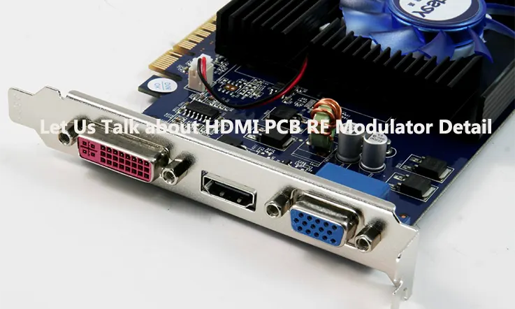
HDMI, an acronym for High Definition Multimedia Interface, is a connection type that permits high-quality audio and visual signal transmission amongst a spectrum of devices such as televisions, Blu-ray players, gaming consoles, and computers. HDMI cables are notably appreciated for their proficiency in concurrently transporting definition audio and visual signals via a singular cable.
Conversely, RF (Radio Frequency) modulation is a technique employed to convert signals from devices into a wireless-transmittable format via airwaves. RF modulators are commonly utilized to convert audio and video signals from devices like DVD players and cameras into a format compatible with TVs and other devices featuring an RF input.
The integration of HDMI and RF modulation enables the wireless transmission of top-quality audio and video signals, facilitating content distribution to multiple TVs or devices without the necessity of additional cables or wiring. This technology proves particularly advantageous in scenarios where running cables may be challenging or impractical, such as in large structures or outdoor environments.
What Does an HDMI PCB RF Modulator Mean ?
An HDMI PCB RF modulator is an advanced apparatus adept at transitioning the HDMI signal from an originating device like a computer or Blu-ray player into an RF signal, apt for wireless broadcasting to any device with an RF input like a television set. This particular denomination, “PCB“, asserts to the makeover that occurs on a Printed Circuit Board, an insulating material foundation with conductive pathways meticulously carved on it.
Typically armed with an HDMI input for utilizing the source device and an RF output for interfacing the requested destination device, HDMI PCB RF modulators are crucial in the reshaping of the HDMI signal into an RF one. This vital transition makes it a feasible operation for any device with an RF input, like a television with antenna input, to receive content.
HDMI PCB RF modulators can come in handy in situations where HDMI cables can’t be practically deployed, like in vast infrastructures or outdoor locations. They can also facilitate distributing content across a multitude of televisions or related devices, abolishing the need for redundant cables or wirings.
How does an HDMI PCB RF Modulator work ?
An HDMI PCB RF modulator functions by converting the digital HDMI signal originating from a source device into an analog RF signal capable of transmission over the airwaves. Housed within a printed circuit board (PCB), the modulator integrates essential electronic components essential for executing this conversion process.
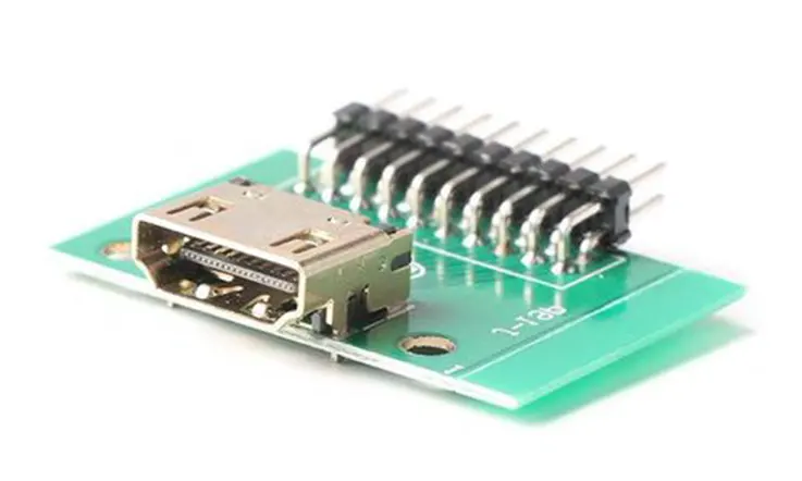
The transformation procedure comprises a series of ordered stages. In the initial phase, the HDMI signal, using an HDMI connector as its primary input pathway, is imported into the modulator. After that, the modulator steps up to regulate the digital signal, instigating its metamorphosis into an analog format appropriate for broadcast over the airwaves.
Continuing from this point, the modulator enlists an oscillator to establish a carrier wave at a predefined frequency. This carrier wave is subject to modulation with the analog signal derived from the HDMI ingress, leading to the production of an RF signal containing both audio and visual data.
Subsequently, the modulator proceeds to amplify and filter the RF signal to ensure alignment with requisite transmission standards. The amplified signal is then routed through an RF connector positioned on the modulator, enabling seamless connection to a TV or any other device featuring an RF input interface. This comprehensive process ensures efficient signal transmission and compatibility across various devices.
When your TV or any other gadget receives an RF signal it essentially captures that signal. Dissects it to retrieve both the audio and visual data. This procedure enables the content being transmitted to appear on your screen as if you had linked the device directly with an HDMI cable.
In summary, the implementation of an HDMI PCB RF modulator facilitates the transmission of premium-grade audio and video signals through the airwaves. This technology enables the dissemination of content to multiple TVs or devices without necessitating supplementary cables or wiring infrastructure. By leveraging this solution, users can enjoy seamless connectivity and enhanced versatility in signal distribution, all while maintaining superior signal integrity and quality standards.
Advantages of Using an HDMI PCB RF Modulator
Wireless Broadcast: One of the fundamental strengths of deploying an HDMI PCB RF modulator lies in its proficiency in performing wireless broadcast of audio and visual information. This sidesteps the necessity for excessive cabling or wiring, a boon in scenarios where implementing such infrastructure proves impractical or unfeasible.
Multi-device Dissemination: A further benefit characteristic to the HDMI PCB RF modulator lies in its capacity to distribute audio and visual data across a multitude of devices. This modulator has the capability to propagate the RF signal to any appliance equipped with an RF input—for instance, a television with an antenna input—enabling simultaneous reception of content by numerous devices.
Cost-effective: Using an HDMI PCB RF modulator can be a cost-effective solution for distributing audio and video content, especially in situations where running cables would be expensive or impractical.
Straightforward Installation: The installation of an HDMI PCB RF modulator is generally uncomplicated and accessible to individuals possessing fundamental technical proficiency. Mounting the modulator onto a wall or similar surface is straightforward, with minimal connections necessary—typically an HDMI input and an RF output suffice for setup.
Versatile Compatibility: HDMI PCB RF modulators exhibit extensive compatibility with diverse device types, including but not limited to Blu-ray players, gaming consoles, computers, and various HDMI-enabled devices. This broad compatibility ensures seamless integration with a multitude of systems, offering flexibility and convenience in deployment.
Design considerations for creating an HDMI PCB RF Modulator
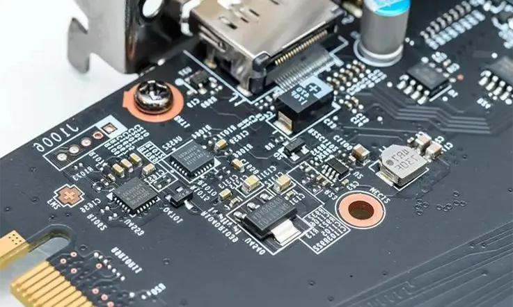
An HDMI PCB RF modulator constitutes a specialized device engineered to transform HDMI signals into RF signals suitable for transmission through the air. This device is predominantly constructed on a printed circuit board (PCB) and incorporates a spectrum of electronic components, including a microcontroller, modulator, and RF amplifiers. These components synergize to facilitate the conversion process, enabling seamless transmission of HDMI content over the airwaves.
Here are some design considerations for creating an HDMI PCB RF modulator:
Component decision-making: Making the right call on component selection can deeply influence the effectiveness of an HDMI PCB RF modulator. Essential components that require meticulous selection encompass the modulator, microcontroller, amplifiers, and filters. The choice of the modulator should hinge on the anticipated output frequency and modulation scheme. Correspondingly, the microcontroller should be picked based on the desired features and the processing power it commands.
PCB layout: The setup of the PCB is utterly paramount to the device’s operational capability. Utmost care should be administered while placing the components, charting out the traces, and devising the grounding scheme. It’s highly recommended to optimize the layout in a manner that trims down signal disturbance and Crosstalk.
Power supply: The power supply is a critical component of an HDMI PCB RF modulator. The device may require multiple voltage levels, and proper power regulation and filtering are essential to ensure stable and reliable operation.
Thermal considerations: Thermal management is a critical aspect to address, especially in devices incorporating RF amplifiers due to their propensity to generate notable heat. In PCB design and enclosure planning, it’s imperative to prioritize arrangements that facilitate effective heat dissipation. This proactive approach safeguards against potential damage or performance degradation, ensuring optimal functionality and longevity of the device.
Compliance with regulatory standards: The design of an HDMI PCB RF modulator must comply with relevant regulatory standards such as FCC and CE. This may include testing for electromagnetic interference (EMI) and compliance with safety standards.
PCB Layout and Component Selection for an HDMI PCB RF Modulator
The PCB layout and component selection are critical to the performance of an HDMI PCB RF modulator. Here are some considerations for these aspects of the design:
PCB Layout
Keep the RF digital and analog circuits separate: In PCB engineering, it’s imperative to maintain segregation between RF circuits and digital/analog circuits to mitigate interference and signal deterioration. This objective is attainable through strategic implementation of ground planes or signal isolation techniques. Such practices are instrumental in preserving signal integrity and enhancing overall performance of the system.
Minimize trace lengths: Shorter traces result in less resistance, which helps to maintain signal integrity. This is particularly important for high-frequency signals.
Use proper impedance matching: Achieving impedance matching is paramount to optimize power transfer and uphold signal integrity. This objective is accomplished by employing transmission lines with precise impedance values. Adhering to proper impedance matching practices is crucial for ensuring efficient signal propagation and mitigating signal degradation within the system.
Use proper grounding techniques: Proper grounding is essential to minimize noise and interference. Ground planes or a star grounding technique can be used.
Shield the PCB: Implementing shielding on the PCB serves as an effective strategy in mitigating the impact of external interference on the signal integrity. This proactive measure is instrumental in safeguarding the circuitry against extraneous disturbances, thereby bolstering overall signal quality and reliability.
Component Selection
Modulator: The modulator stands as a pivotal element within an HDMI PCB RF modulator setup. Its selection process warrants meticulous attention to key factors including output frequency, modulation scheme, and power requisites. These considerations are fundamental in ensuring optimal performance and compatibility within the overall system architecture.
Microcontroller: Serving as the device’s nucleus, the microcontroller holds the duty of administering the modulator and affiliated components. The microcontroller’s choice should depend on the desired function, handling capacity, and its congeniality with the selected modulator.
RF Amplifiers: RF amplifiers constitute a critical component aimed at bolstering the strength of the modulated RF signal. The choice of RF amplifiers is contingent upon factors such as desired power output and frequency range, necessitating meticulous selection to align with the device’s specifications.
Filters: Filters serve as indispensable tools in mitigating undesirable noise and interference from the signal. The selection of appropriate filters is contingent upon the unique requirements of the device, necessitating a tailored approach to effectively eliminate unwanted distortions.
Passive Components: Passive Elements: Passive elements, which could include resistors, capacitors, and inductors, are utilized to sift and mold the signal. The choice of these components should hinge on their technical details and their harmonization with the remaining components.
Testing and validation of an HDMI PCB RF Modulator
The procedures of examination and verification hold critical roles in the blueprint process for an HDMI PCB RF modulator. These steps guarantee that the device adheres to the needed specifications and efficacy standards. Below are some methodologies implemented for such testing and verification:
Functional Verification: This essentially relates to executing an operational examination of the apparatus to validate its functionality accordance with its design intentions. It can be realized by interfacing the device with suitable input/output peripherals and corroborating the rectitude of the output signal.
Signal Assessment: This pertains to the quantification of the device’s output signal to ensure its compliance with the desired specifications. It can be exercised via deploying measurement tools such as an oscilloscope, spectrum analyzer or alternative testing machinery.
Radio Frequency (RF) Performance Evaluation: This encapsulates the inspection of the device’s RF efficacy, incorporating parameters such as output power, the span of frequency, and modulation traits. The requisite procedures can be carried out via sophisticated RF testing gear.
Environmental testing: Environmental testing is essential for evaluating the device’s resilience under varying environmental conditions. By subjecting the device to different temperature and humidity levels, we ascertain its reliability and stability in diverse operating environments.
Compliance testing: Compliance testing is crucial to ensuring our devices adhere to regulatory standards such as FCC and CE. This encompasses rigorous testing for electromagnetic interference (EMI) and compliance with safety standards to guarantee our products meet industry regulations.
User testing: User testing is a key aspect of our development process, allowing us to gather valuable feedback from end-users. By engaging users in the testing phase, we ensure our devices are user-friendly and effectively meet their requirements, enhancing overall product satisfaction.
Buying Considerations for HDMI PCB RF Modulators
When considering buying an HDMI PCB RF modulator, there are a few important factors to consider:
Conformity: Ascertain that the HDMI PCB RF modulator synchronizes with your distinctive apparatuses and systems. Validate the stipulations to ensure it upholds the requisite input and output resolutions, as well as any necessary auxiliary features or functions.
Quality: Look for a high-quality HDMI PCB RF modulator that is built with durable materials and components. This will ensure that it can withstand regular use and provide reliable performance over time.
Financial Consideration: Evaluate the fiscal aspect of the HDMI PCB RF modulator, ensuring its alignment with your financial constraints. Bear in mind that models at a higher price point may present added functionalities or superior performance, whereas those at a lower price point might offer fundamental features.
Brand and reputation: Choose a reputable brand with a good track record for producing high-quality HDMI PCB RF modulators. Read reviews and do your research to ensure that you are buying a product that has a good reputation among other users.
Warranty & Assistance: Assure to scrutinize the warranty and support provisions extended for the HDMI PCB RF modulator, confirming your satisfaction in the quality of support offered. Opt for devices supplemented with a warranty or a guarantee clause, and contemplate procuring from a firm noted for its superior customer services and assistance.
Installation and setup of HDMI PCB RF Modulators
The process behind the installation and setup of an HDMI PCB RF modulator can diverge based on the distinct model and the apparatuses being employed. Nonetheless, enclosed is a construct of the prevailing steps to facilitate this operation:
Selection of Ideal Locale: Settle upon a locale for the HDMI PCB RF modulator, which finds itself in close proximity to the devices targeted for connectivity. Guarantee adequate space to position the modulator as well as to accommodate necessary wiring.
Establishing Connection Between the Devices: Commence by bridging the HDMI source gadget, perhaps a Blu-ray player or a gaming system, with the HDMI inlet situated on the modulator, facilitated through an HDMI cable. Simultaneously, inaugurate a connection between the RF outlet on the modulator and the RF inlet on your television display or any other appropriate device, executed via a coaxial cable.
Activation of Devices: Energize the HDMI source as well as the television or the alternate device poised to receive the signal. Ensure that the modulator itself is powered on.
Modulator Setup: Employ the settings interface of the modulator to dictate the output specifications, such as the channel frequency and resolution. For distinctive guidance on accomplishing this task, the user manual should serve as an integral reference.
Calibrate the Television or Equivalent Device: Leverage the respective device’s calibration feature to accommodate the frequency established on the modulator. This may necessitate employing the remote of the television to scan accessible channels or inputting the channel number manually.
Signal Verification: Subsequent to the connection and configuration of the devices, conduct a signal audit to ensure its proper functionality. Safeguard the picture and audio quality is devoid of disruption and possess clarity.
Refinement of Settings: If deemed necessary, reconfigure the modulator’s settings or alter the alignment of the devices to enhance signal quality.
Content Appreciation: Upon conclusion of the installation and setup, savour your HDMI content across numerous devices without the prerequisite for extra cords or wiring.
Troubleshooting common issues with HDMI PCB RF Modulators
Here are some common issues you may encounter with an HDMI PCB RF modulator and some troubleshooting tips:
●Signal Disruption on TV: In instances of signal loss on your television or related devices, it is recommended to meticulously inspect the integrity of all cable connections, ensuring proper power supply to both the modulator and associated devices. Confirming that the television is accurately tuned to the designated channel or frequency, and validating the correct configuration of the modulator are essential steps.
●Poor signal quality: When you’re dealing with signal performance it’s advisable to try adjusting the position of your devices or antenna to boost signal strength. You might also have to make some tweaks to the modulator settings, for signal quality.
●Interference or Noise Disturbances: The presence of interference or noise within the signal necessitates a systematic approach. Mitigating such disturbances involves relocating devices or antennae away from potential sources of electromagnetic interference, including other electronic apparatus or household appliances.
●Incompatible devices: When you are encountering compatibility issues, it is imperative to verify the compatibility of all devices with the modulator and ensure their correct configuration. To address this concern, referring to the user manual is advisable as it provides specific instructions on how to ascertain compatibility and configure the devices accordingly.
●Power-related Anomalies: Addressing aberrations in modulator functionality mandates a methodical approach. Evaluating the viability of the power supply unit or the modulator itself is prudent. Double-checking the modulator’s connection to a reliable power source and verifying the operational integrity of the power supply unit are indispensable troubleshooting measures.
Conclusion
HDMI PCB RF modulators serve as a beneficial tool for wirelessly transmitting top-tier audio and video signals via airwaves. They offer a convenient and cost-effective solution for distributing content to multiple devices without the need for additional cables or wiring.
The continuous advancement of technology suggests that there will be improvements in HDMI PCB RF modulators resulting in better resolutions and faster transmission rates. Furthermore, advancements in the design and capabilities of these devices are expected, potentially involving the incorporation of wireless technologies such as Wi-Fi and Bluetooth.
Related Posts:
1.Guide to RF PCB Design and Microwave Material Selection
2.As a PCB Electronics Manufacturer: You Need to know Everything About RF Amplifier
3.RF Multiplexer: Design, Types, Functions and Applications