Circuit boards with integrated circuits (ICs) are practically inseparable from modern technology. Integrated circuits are most commonly found in high-density computer chips that aim to maximize the amount of space devoted to each component. They can be found in almost all of the modern electronic products and infrastructures.
Therefore, it is necessary to have a comprehensive understanding of circuit board ICs if you are an end-user or a circuit designer. Continue reading to learn more about the many varieties, how they operate, the production methods, and other relevant information.
What is an IC Board?
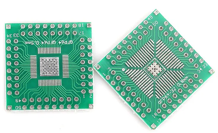
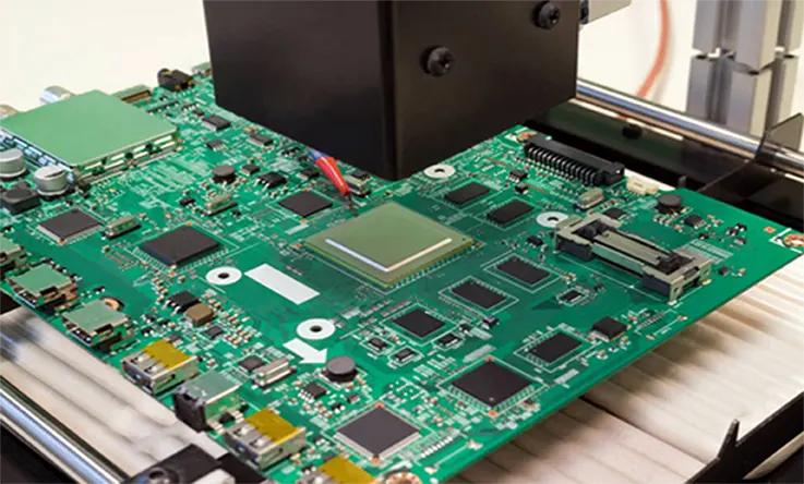
An integrated circuit board (IC board) is a specific kind of printed circuit board assembly (PCBA) that has integrated circuits (ICs) installed on the board. In most cases, you will solder an integrated circuit (IC) to the surface of the printed circuit board (PCB) assembly and the wires that are attached to it.
How do Integrated Circuit (IC) boards work?
The connections of the components enable the IC boards to function. Most of the time, their shapes and sizes are determined by the degree of integration intended for the board. Ultra-large-scale integration with billions of components is used in the billion-transistor processor era. It distinguishes between small-scale and medium-scale integration, which involves thousands of transistors.
The most common base technology is CMOS integrated circuit technology. However, one feature that all ICs share is the interconnection of wires that connect all of the components.
When connecting components to external devices, it is possible that mechanical assistance will be necessary at times. For this reason, some boards incorporate a frame or structure that allows for the connection of internal and exterior wires. In other circumstances, the IC boards provide the necessary electrical assistance to maintain the integrity of the electrical connection between the components.
IC Board Manufacturing Process
IC board : Choose the best design
When making an integrated circuit board, the first thing that must be done is to select the design that will work best. Before making a choice, it is strongly suggested that you give careful consideration to all relevant aspects of the situation. This will guarantee that nothing will go wrong. You should think about the kinds of components you will employ, the quantity of those components that will be included in the design, and the amount of space that each component would require. You will be able to make the best choose when you keep all of these considerations in mind.
IC board: Choose a PCB manufacturing company
Once a PCB designer completes a layout for a board that will work in producing a certain product, the next step is to figure out how to actually make the board. There are a few options, so think this through carefully before deciding. When deciding on a manufacturer, it’s important to weigh the company’s manufacturing procedures, output capacity, and service pricing in light of your needs. When you outsource the assembly of your product to a global manufacturer like JarnisTech PCB and Assembly, you can rest assured that it will meet or exceed all applicable quality standards thanks to their presence on a global scale.
IC board: Choose each design to manufacture
When selecting a PCB design, the designer needs to be aware of the manufacturing process in order to make an informed decision. This technique is highly critical. In the event that he does not do so, he runs the risk of selecting the inappropriate one for this product or of causing manufacturing issues. These issues may arise as a result of the fact that he does not take into account the complete procedure involved in the manufacturing of the board. In the event that this takes place, he will make blunders in both the design and the manufacture of the product.
IC board: Choose suppliers for components
Following the process of selecting the PCB manufacturing firm and designs, an engineer is required to compile a list of component suppliers. After that, he can approach them with his design requirements and request that they supply him with the necessary components.
IC board: Creating an assembly procedure
After all of the product’s components have been received, an engineer will need to devise a method of assembly in order to evaluate this product’s operational capabilities. Additionally, it is necessary for him to conduct tests on the boards in order to determine whether or not the manufacturing procedure is functioning appropriately.
IC board: Final Steps
The final step in the process of generating an IC circuit board is checking all of the design aspects of the component. This phase is extremely important because it will assist the engineer in making the most out of this product in the right way.
An engineer needs to take into account everything that has to do with the production of a product before he or she can decide which design is best to use.
What are the features of IC?
The term “integrated circuit” refers to a small electronic component. The transistors, resistors, capacitors, and inductors necessary for a circuit are interconnected using a specific technique on a tiny semiconductor wafer or dielectric substrate, and then packaged together. When all the parts of an electronic component are merged structurally, the result is a microstructure that performs the necessary circuit function. This is a significant advancement toward miniaturization, low power consumption, intelligence, and high reliability. The letter “IC” stands for it in the circuit. Jack Kirby (using germanium; Ge) and Robert Neuss (using silicon; Si) are the inventors of the integrated circuit. Integrated circuits made of silicon are used in the vast majority of today’s semiconductor applications.
The benefits of the integrated circuit are low cost, ease of mass production, and a long lifespan, excellent reliability, good performance, few lead wires and solder connections. Tape recorders, televisions, computers, etc., as well as the military, communication, remote controls, and other areas of electronic equipment, make extensive use of this technology. When compared to using transistors, the assembly density of electronic devices built using integrated circuits can be raised by a factor of tens to thousands, and the devices’ ability to maintain a steady state for longer periods of time during operation is also substantially enhanced.
What are the Types of ICs?
The following is an in-depth explanation of a few of the most common types of integrated circuits.
Classification: Package based
MCM IC Substrate: One type of integrated circuit (IC) is known as a multi-chip module, also known as an MCM IC substrate. This type of IC integrates a chip with a variety of functionalities into a single package. This is the outcome of the product having ideal performance thanks to its many features such as miniaturization, shortness, thinness, and lightness, amongst others. Because so many chips are being packaged onto a single package, the sort of substrate being used does not perform particularly well in terms of signal interference, routing, or thermal dissipation.
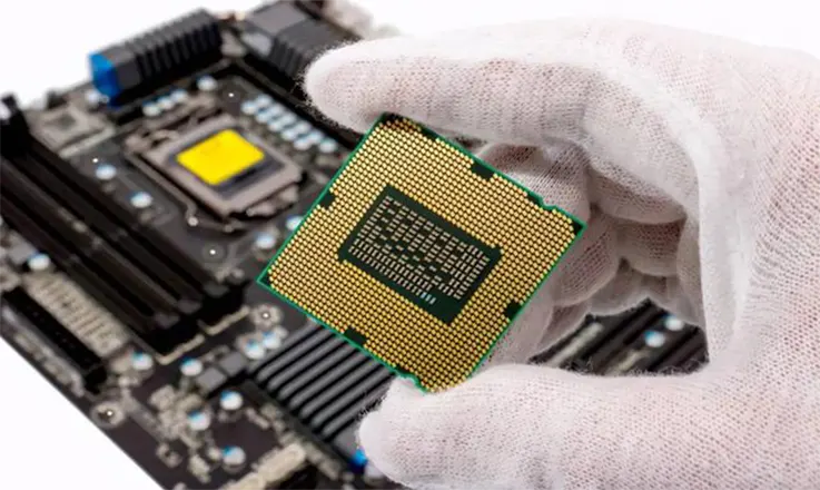
BGA IC Substrate: These integrated circuits function best when their heat is dissipated. Electrically, it performs incredibly well, and it has the potential to significantly expand the number of pins on-chip. Because of this, ICs with more than 300 pins are the greatest candidates for such packaging.
FC IC Substrate: Flip Chip, also known as FC IC, is a type of packaging that is acquired through the process of flipping chips. This type of packaging offers several advantages over traditional methods of chip packaging, including a lower signal interference ratio, lower losses in the circuit, higher performance, and efficient thermal dissipation.
CSP IC Substrate: An integrated circuit like this one is made up of a single chip that has been packaged together. It is scaled down to a smaller size, has a lower weight, and provides nearly the same functionality as an IC. These types of integrated circuit substrates are typically used in devices that contain memory, such as those used in the telecommunications sector and the electronics industry, particularly in situations where only a limited number of pins are required on-chip.
Classification: Material based
Ceramic IC Substrate: Ceramic materials like as silicon carbide, aluminum nitride, aluminum oxide, etc., are used in the primary production of such integrated circuits. It has a relatively small coefficient of thermal expansion, somewhere in the range of 6–8 ppm per degree Celsius.
Rigid IC Substrate: An IC of this kind can be fabricated using epoxy resin, ABF resin, or BT resin, or all three. The thermal expansion coefficient of such an integrated circuit is between 13 and 17 ppm per degree Celsius.
Flex IC Substrate: An integrated circuit like this one can be produced using PE or PI resin, and its coefficient of thermal expansion ranges from 13 to 27 ppm per degree Celsius.
Classification: Bonding Technology-based
The following is a significant classification based on the application of bonding technology:
●FC bonding.
●Wire bonding.
●Tape automated bonding.
How do I install IC?
Leads and their respective pinouts are contained within an integrated circuit. In addition, prior to installing the integrated circuit, it is quite beneficial to spend some time familiarizing oneself with the various leads. A lead has an internal connection that is connected to another pad on the PCB or to another device.
Solder is the most common method for connecting leads to pins on an integrated circuit (IC), however leads can also be attached to pins via wire bonding, wire-bonding pins, or metal plating on the leads.
Sometimes, Epoxy or resin can be used occasionally as a substitute for the traditional method of attaching integrated circuits to printed circuit boards (PCBs).
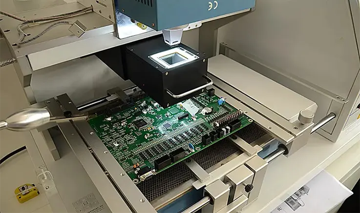
The first step that needs to be done is to get the printed circuit board (PCB) and any other pieces of equipment, like conduits and power supply modules, ready to be connected. The second phase should be selecting and designing the IC, as well as any connected components and wiring (other ICs or parts on the PCB or devices like diodes). Soldering is the final step in completing the assembly of electronic parts and connections.
IC Boards : Installation Process
Follow these design criteria precisely before installing an IC board:
1.Before beginning the assembly process, you need to make sure you have all of the necessary tools ready. The soldering iron is an important piece of equipment to have here. The temperature should be between 220 and 270 degrees Celsius; exceeding this range would cause the insulation to break down, lead to thermal shocks, and eventually cause damage to the IC material.
2.Ensure that the component leads are not scratched. For example, using metal tweezers causes harm to the authorities and increases the risk that they may break off.
3.Avoid using static electricity inducers, such as a hairdryer, on the IC pins.
4.Avoid making unnecessary contact with the surface of the integrated circuit. For example, too much solder and flux can cause the board to become damaged.
5.The integrated circuit should never be subjected to situations that involve bending, twisting, extreme heat, or dampness.
6.Finally, a test run on the IC is necessary to finish the coupling. Such a check verifies that the circuits or devices are functioning properly.
Types of damage to common ICs and Safeguard Procedures
Integrated Circuits (ICs) that are mounted on Printed Circuit Boards are susceptible to two primary forms of damage: physical damage and electrical damage. However, there are numerous other forms of damage to ICs that do not fit well into either of these categories (e.g., misapplication, inappropriate handling, etc.).
Physical Damage
One form of physical damage is the bending of circuit boards, which can short out components. Because of this, the flexing star points (little metal pins connecting the board to the IC) often become bent or broken.
Electrical Damage
The solder joint that connects the leads of the IC to the pads on the PCB might be compromised by electrical damage. It is possible for it to cause a short circuit or an open circuit. In most cases, bent leads connecting to other pads characterize a short circuit, whereas broken leads characterize an open circuit.
Safeguard Procedures
● Because integrated circuits are extremely delicate and easily damaged by vibration or shaking, you need to handle them with extreme caution. The reason for this is that an integrated circuit is extremely fragile and small, making it susceptible to damage if it is dropped or struck by debris.
● Individual ICs can be easily damaged by exposure to particular substances. For instance, exposing some integrated circuits (ICs) to solvents can wreak havoc on their functionality. Take extra precautions to ensure that they are not placed in any areas where they could be exposed to potentially harmful chemicals.
● When we are mounting the IC on the circuit board, we need to exercise caution. After applying flux to the pads and leads of the integrated circuit, you should then use your index finger or your thumb to firmly press the leads down onto their pads.
● Ceramic packages are used for some integrated circuits, and we need to exercise caution when handling them. They are extremely delicate and prone to shattering if they are dropped or come into contact with any kind of material.
●Some integrated circuits use a polysilicon packaging, which causes them to be fragile if they are directly inspected. This occurs as a result of the package heating up to a large degree.
● When working with these sorts of integrated circuits (ICs), you need to exercise extreme caution since it is quite easy for them to become broken or to break off during the process of handling, and they may also overheat and potentially become damaged due to the excessive heat.
IC Boards : Work Mechanisms
The mechanism of an integrated circuit board is dependent on a sturdy and reliable device foundation in order to connect a chip made of semiconductor material. Electronic engineers can more easily install a variety of devices that use one or more integrated circuits with the assistance of the IC boards.
The majority of IC boards just require a single power supply to run all of the connected devices. Therefore, if there is a problem with the connection on the IC board, it will have an effect on all of the components that are connected.
IC Board Vs.PCB Board
An integrated circuit is a tiny electronic circuit. When compared to the IC, the internal chip is quite small, making it difficult to connect directly to the PCB. On the other hand, the IC can be linked to the PCB with relative ease. An integrated circuit (IC) is the name given to the portion of the motherboard that contains both the northbridge chip and the CPU. Its original name was an integrated block.
PCB is a material that is utilized in practically all electronic devices. PCBs of varying sizes are put on circuit boards in any device that contains electronic components. The primary role of printed circuit boards (PCBs), in addition to securing smaller components, is to connect one another.
In a nutshell, an integrated circuit is the culmination of the integration of multiple conventional circuits into a single chip; it is a unit. When the chip’s internals are damaged, the chip itself will also be harmed. Printed circuit boards (PCBs) are used to connect integrated circuits and discrete components so that a larger functioning circuit can be created. The printed circuit board (PCB) itself is capable of soldering components and, in the event that it becomes damaged, replacing components. In the days before printed circuit boards (PCBs), components were “point-to-point wired,” meaning that wires were utilized to connect each component directly to the next. In comparison to PCBs, this approach was unreliable and a headache to implement. You can watch the video that has been provided below for more information in-depth.
Application of ICs on PCBs
Integrated circuits (ICs) typically have leads integrated inside of them so that they may be attached to circuit boards. There are three primary categories of application patterns that are typically found on circuit boards:
Through Hole: This sort of PCB usage is not as prevalent as surface mounted, but we use it in more sophisticated PCBs that require lots of IC connections. This type of PCB usage is typically utilized on less space-sensitive equipment.
Surface Mount: This kind of application is used for the vast majority of integrated circuits (ICs). In most cases, we find them on machinery that has a limited amount of available space, such as printing machines, medical equipment, packaging gear, and other similar types of machinery. We are able to locate this kind of circuit board with any IC installed on it.
Hybrid: This form of connection typically employs a combination of through-hole and surface mount connections to the integrated circuit (IC).
Applications of the circuit board IC
The application of the integrated circuit board is extremely widespread. The following are some examples of them:
Medical: The use of circuit boards in medical equipment is also very beneficial to that industry. You can find them in a variety of medical devices, including as endoscopes, blood pressure monitors, X-ray machines, and so on.
Automation: In general, circuit boards are helpful in the automation of processes for both the makers and the end consumers of these products. Robots, packaging lines, printing machines, timers, and other devices are all examples of automation applications that make use of circuit boards.
Industrial control: As we know, its importance cannot be overstated in the context of industrial procedures. Consequently, industrial robots, automated control systems (ACS), forklifts, and factory automation can all profit from the use of microcontroller circuit integrated circuits.
Miscellaneous Electrical: In general, the functionality of a significant number of electrical devices is dependent on integrated circuits (ICs). A circuit board is required to control the electrical signals that are applied in order for the lights, fans, and remote controls to function properly.
Test: In a similar vein, they are useful in the areas of instrumentation, test chambers, measurement equipment, and so on.
Vacuum: They are common components in specialist equipment, such as those used for servicing and maintaining vacuum systems. Applications such as these vacuum systems are helpful additions to food processing factories as well as warehouses.
Mechanical: In addition to their use in electronic devices, IC boards are also commonly found in mechanical and assembly line equipment. Conveyors, robotic arms, pick-and-place units, and other specialized machinery are all included in this category.
How to choose a Perfect Circuit Board IC?
A circuit board’s main function is to join together the parts of a single power supply unit. So, let’s talk about how to pick the perfect circuit board ICs for you:
● The first step is to pick a decent design that supports the function of your circuit board IC. These factors include the price of the materials required, the sizes of the components, and the simplicity of fabrication.
● Additionally, make sure you are familiar with the features and operation of the PCB design you have chosen.
● Once more, confirm that the manufacturing procedures adhere to the necessary criteria.
The PCB engineer should be well-versed in all of these processes. Therefore, it works as intended when he uses these unique design strategies.
Summary: Why Choose Us
JarnisTech, which specializes in prototype and production volumes and has been the industry leader in quick turn PCB manufacturing since 2003, first developed single- and double-sided printed circuit boards for the consumer electronics sector. Among the top 4 board fabricators in Asia, JarnisTech is renowned for its ability to complete orders quickly and for consistently completing shipments on schedule.
Today, we have over 1500 workers and ultra-modern facilities to produce multi-layer PCBs with anywhere between four and sixty layers. supporting with a team of qualified engineers and an established quality system JarnisTech has developed into a significant PCB producer in Asia, serving a variety of markets including electronics for appliances, communications, education, power supplies, automation, etc.
Our goal is to become a producer of printed circuit boards that offers one-stop service, specializes in providing products of the highest possible quality, and is committed to achieving complete and utter satisfaction for our clients