If you are making a robot or any other kind of electronic project, it is possible that you will prototype the wiring on a breadboard first, and then you will fabricate a permanent circuit on either a perforated board or a printed circuit board. This could happen regardless of whether you are working on a robot or another kind of electronic project. In addition to this, the majority of its functions will be controlled by a board. When it comes to the fabrication of the board, the electronic designers are aware of the various types of boards that are available and can recommend the one that would work best for your electronic project.
Breadboards and printed circuit boards (PCBs) are the two primary forms of circuit boards that can be fabricated. In point of fact, one is utilized rather frequently in tailor-made and one-of-a-kind tasks, whereas the other is suitable for more generic types of projects. Because each one serves a unique purpose, there is no one that is superior to the others; rather, it is up to you to determine which one is necessary based on your requirements.
What Is a breadboard?
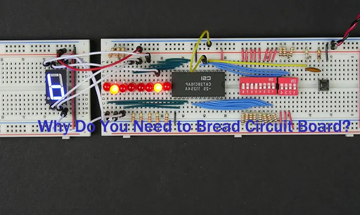
Breadboard, sometimes referred to as protoboard, is the most common type of board used in do-it-yourself electronic projects. A breadboard is a straightforward piece of equipment that eliminates the need to solder connections between components in electrical circuits. It is a piece of rectangular plastic board that has a number of very small holes punched all over it. Because of the holes, it is simple to insert electronic components into the board to create a prototype of an electronic circuit, such as the one shown here, which includes a battery, switch, resistor, and LED (light-emitting diode). Breadboards, on the other hand, will have a less permanent connection than printed circuit boards will, meaning that you will be able to remove and replace breadboards as necessary because they feature sockets that the components can be pushed into. Before the circuit connections are made to be permanent, it is unavoidable that a breadboard will be utilized more for experimenting, designing, and testing the connections.
History of the Breadboard
Early in in the history of electronic engineering, radio and electrical freaks prototyped their circuits on actual bread boards, which were essentially bread cutting boards.
Wikipedia: In the early days of radio, amateurs would solder electronic components to a wooden board that had bare copper wires or terminal strips nailed to it (often literally a cutting board for bread). The board would then be used to transmit radio signals. Sometimes a paper schematic diagram was first glued to the board as a reference to inserting terminals. After that, components and wires were installed over their symbols on the schematic. Occasionally, this process was reversed. In addition, it was usual practice to use thumbtacks or small nails as mounting posts.
You might believe that this neanderthal method is out of date, yet there are still a few valid reasons to employ it, such as in educational settings.
Why Do You Use a BreadBoard?
As was said before, a breadboard is useful because it enables you to rapidly and temporarily put up circuits in order to test them. After determining how the circuit functions on the breadboard, you can then proceed to set up a more permanent configuration. Hobbyists and tinkerers can use them to set up projects as a standalone device, or as a peripheral to an Arduino, Raspberry Pi, LaunchPad, BeagleBone, or one of a wide variety of other development boards. They are a terrific resource. They are available in a variety of sizes to accommodate a wide range of jobs. Breadboards are likewise relatively affordable, and the components that are compatible with them are often not much more expensive. If you want to make your project more permanent, it is easier to move from a design on a breadboard to a design on a protoboard or PCB rather than jumping straight to those boards that are more difficult to manage.
In the field of electronic design, you will inevitably come across breadboards, regardless of whether you are just starting out or have made significant progress. Learning about their benefits, such as the speed and ease with which circuits can be created, as well as their drawbacks, such as their transience and their restrictions in terms of the amount of power they can handle and the RLC (resistance, inductance, and capacitance) effects they produce, will enable you to create many projects in the future that are both entertaining and practical.
Functions of a Breadboard
Breadboards, unlike what the majority of people would assume, continue to be an extremely useful tool in this day and age. It is no longer implying a breadboard made of wood and stuffed with wires and conductive posts, but rather one that uses solderless circuits. As a result, the breadboard is an extremely useful tool for prototyping as well as creating temporary circuits. In addition to this, they do not require any soldering to be done. What exactly does it mean to prototype something?
Prototyping
It refers to the process of testing a concept by creating a pilot model that serves as a template for creating more forms. The process is critical, and a breadboard is a key enabler. Prototyping is extremely beneficial when it is impossible to predict how a certain circuit will perform under stated settings.
Beginning with breadboards may be the best option for you if you are unable to understand how circuits function but are still interested in learning about them.
The testing of new components
When it comes to testing new components like integrated circuits, a breadboard transforms into the ideal platform. However, in order to test the components, you will need to wire and then rewire the components in order to determine the proper pattern and stay away from soldering.
Troubleshooting function
When trying to duplicate a customer’s issue and figure out how to solve it, a breadboard can be an extremely helpful tool. As a result, the temporary nature of this breadboard makes it an ideal choice for performing these duties.
What Makes a Breadboard?
If you wish to comprehend the functionality of a breadboard, you must disassemble its components. To make it easier for you to comprehend how the breadboard acts as a whole, I describe each component and its individual role in this section. So let’s dig right in.
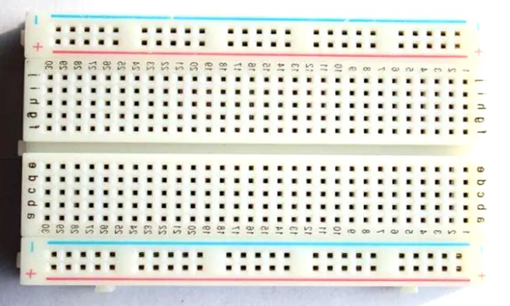
Terminal Strips
Under the holes of a breadboard, the metal rows that comprise the breadboard connection feature little clips. Every socket and metal strip can be arranged with a standard pitch of 2.54 mm between each one. These clips facilitate the insertion of connecting wires and component leads into breadboard holes.
When any component is placed on a breadboard, the power source can be supplied to any hole in that row, as these holes are conductive and permit the flow of current from any end of the strip. Each strip on the breadboard contains five clips, allowing us to connect five components within a single area of the breadboard.
Each row on the breadboard has ten holes, and each row can be separated by a fissure or ravine in the center of the breadboard. This ravine separates both sides of the rows, and they are not electrically connected.
Power Rail
In addition to the rows of terminal strips that are arranged horizontally across the breadboard, there are also power rails that are arranged vertically along the sides of the board. These rails, much like the terminal strips, conduct power, but they also all link to one another. The process of connecting to power is made easier if the wires are consistently colored blue, black, or red to indicate whether they are positive or negative. However, keep in mind that the two power rails that are positioned on either side do not connect to each other. Therefore, whenever you want to use a similar power source, you will need to link them using jumper wires so that they can share the power.
Columns and Rows
Breadboards have rows and columns that are denoted by letters, and these letters are visible to us. These prove to be quite useful during the process of creating a circuit on the board. In the event that the component on this board is moved inadvertently, the circuit may quickly become complicated; nevertheless, if it is not moved, the circuit will not function at all. If you first locate the row number on the breadboard that corresponds to the connection, installing the component on the board will be a piece of cake.
On the breadboard, the connection of the circuit does not need to be in the correct spot as depicted in the design. This is because the breadboard is not an exact replica of the circuit. In point of fact, it need not even have a comparable appearance. You are free to construct your circuit as you choose provided that all of the connections to the circuit are finished.
DIP Support
The sides of a breadboard are split by a ravine, which also serves an important purpose in the process of disconnecting connections. Chips are made to have dimensions that are compatible with these breadboards, and they are then packaged in DIP (dual in-line package). DIPs have legs that are designed to fit into the ravine, and due to the fact that every DIP chip leg is unique, the separation that the ravine provides assures that the legs do not connect with one another.
Binding Posts
Breadboards can come with binding posts, which allow them to act as linking towers for a variety of different power sources.
Other important elements of the breadboard are the side slots and the small nubbins. These elements allow you to connect your circuit even if it requires more space than is available on the surface of the board. In addition to this, it will enable you to connect the breadboard to additional breadboards so that the total surface area of the circuit can be increased.
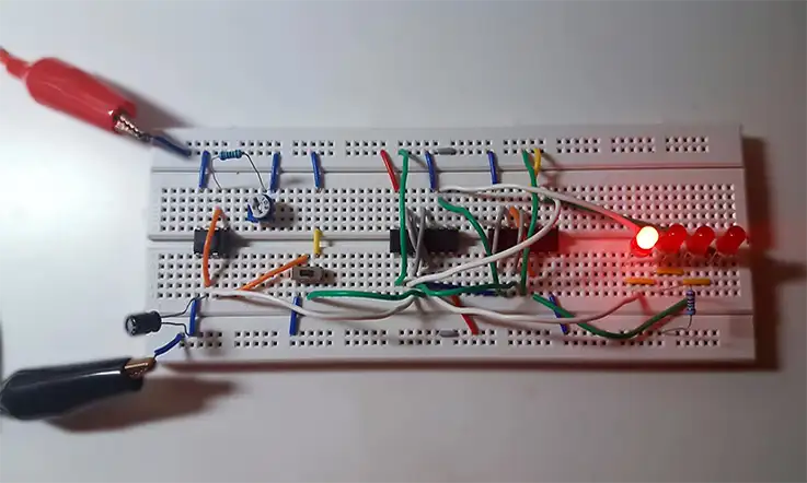
How to Build a Circuit On a Breadboard
Depending on the components you wish to incorporate, breadboard circuits can be assembled in a variety of ways. For a simple circuit, however, the first step is to have all the required components, such as a resistor, button, LED, power source, etc. Then, you must comprehend the numerous connections in order for the breadboard circuit to function. Here, a circuit diagram, regardless of its intricacy or simplicity, becomes indispensable. It will enable you to comprehend what relationships exist and in what order. There are already free software packages that can be used to virtually build a schematic.
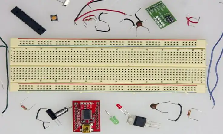
● A breadboard is a flat set of small sockets arranged in columns and rows built into a stable and non-conductive base. It gives you the ability to quickly test circuit design without the need to break out your soldering iron. Whether you are an electronics hobbyist, student, or technician, you will occasionally want to build a temporary circuit with breadboard. Any leads or wires that are introduced into the points in each column get electrically connected to one another due to the fact that the points in each column are already interconnected to one another. On the breadboard, adjacent columns are separated from one another by an insulating barrier.
● The breadboard is divided into a major area in which you create your circuit and a smaller power bus portion in which the buses are organized in horizontal rows. The main area of the breadboard is bordered by a smaller power bus section. In the main part, there are also horizontal slots that are built specifically for integrated circuits. After cutting segments of solid insulated wire with a gauge of twenty-two into jumper wires with lengths ranging from two to ten inches, stripping around half an inch of insulation from both ends of each jumper wire, you should have at least thirty jumper wires.
● First, ensure that the adjustable DC power supply is turned off. Next, place one end of a pair of banana cables in the positive (red) and ground (black) connectors of the breadboard. Finally, place the other end of the banana cables in the appropriate banana binding post jacks on the appropriate breadboard. After tightening both binding posts, insert the other end of each wire into a separate power bus row. A length of jumper wire measuring between three and four inches should be inserted into the little horizontal hole of each binding post.
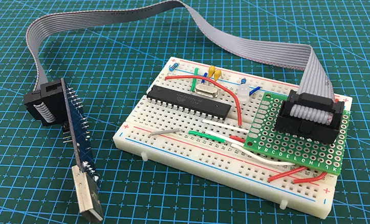
● If you have integrated circuits, you should insert them into the breadboard and apply just enough pressure to fix them while ensuring that none of the pins on the integrated circuit flex. When positioning the integrated circuits, you want to make sure that the key tab or dot points in the left direction. The slots in the plastic of the breadboard should be straddled by the integrated circuits so that each of the pins on the integrated circuit can be electrically isolated from the others.
● While keeping the row-column connection pattern in mind, place the remaining components into the breadboard holes. If you need additional connections but a column has no more holes, all you need to do is put a jumper wire between that column and one that isn’t being utilized. After that, make connections between the power bus holes and the areas of the circuit that need DC power and ground by using jumper wires.If the circuit contains outputs, longer jumper wires should be inserted into the outputs, and then the outputs should be connected to the necessary external equipment.
● Verify each connection on the breadboard and repair any misplaced wires or components. Adjust the power supply’s current and voltage to match your circuit design, then switch it on and test it. If you need to make additional changes, you must turn off the power source, make the modifications, and then turn it back on.
Breadboard Vs Printed Circuit Board
On the one hand, a breadboard is typically the first step in the creation of a printed circuit board. With a breadboard, you can modify and relocate circuits that are otherwise permanent on a PCB.
In contrast, breadboards are used for design and inquiry, while boards are for your final products.
Printed Circuit Board: Advantages
● There is widely used in electronic devices.
● The board is permanent to have an electronic device worked.
● You can mount heat-sinks to the board so that have them rigid.
● A PCB has a cleaner look than a breadboard (when manufactured correctly).
● You can add terminals to your printed circuit board for external connections.
● Nobody is going to buy your great, fantastic, electronic design (product) on a breadboard.
● It is normally easier to understand the circuit on the board. None of those looping wires going everywhere.
● PCB has a better current carrying capacity comparing to a breadboard, you can make your traces wider to take more current so that work well.
Breadboard: Advantages
● It’s easy and fast to assemble as there are no permanent solder connections.
● You can also change various components such as the capacitor or resistor value.
● You can rapidly change connections and test various plans in a development phase.
● You can add an ammeter anywhere with shifting wires (breaking into) any branch of your circuit. ● In addition, the current measurement on PCBs necessitates breaking tracks or adding additional resistors to the design.
Types of Breadboard
Breadboards can be divided into two distinct categories, including solderless breadboards and breadboards that can be soldered.
Solderable Breadboards
Your electronic circuits can be set up in a way that is permanent with these types of breadboards. Breadboards of this type provide for a more robust arrangement. It has holes for electronic components such as copper tracing and incorporates the holes. These components can be soldered using a soldering iron in order to solder the components to the breadboard and create an electrical connection through the copper trace. This connection can be made using the soldering iron.
When creating a circuit, jumper wires are required to be soldered individually in between these various components in order to provide a path that will allow for the flow of current. These types of breadboards can be purchased in a range of sizes to accommodate a variety of requirements.
Advantages:
● Less cost and saves time while designing a circuit.
● These breadboards are robust and your circuit will be very secured.
● This type of breadboard imparts a more specialist look to your project.
Disadvantages:
● This board cannot be reused.
● De-soldering may damage components if a fault occurs in the circuit.
Solderless Breadboards
This is the most popular breadboard for testing and prototyping electronic circuits without soldering the components. There are a variety of sizes, shapes, and ratings available.
Because the circuits on these breadboards are not permanent, we may verify and test the functionality of a circuit before committing to its design on a PCB. The holes in the rows and columns of these breadboards accommodate component leads and wire gauges.
If the terminal of the component does not place into the hole of a breadboard, a connecting wire can be attached to the lead of a component that will fit into the breadboard hole.
Advantages
● It doesn’t require soldering to connect the components on board.
● If the circuit is not functioning properly, we can easily examine and correct it by removing the components and replacing them.
Disadvantages
● These breadboards are restricted to below or 10 MHz frequencies.
● The components attached to the breadboard may become loose if the board is pushed or moved.
● Because of the capacitances between different components that are close to each other, this type of breadboard has significant parasitic capacitances.
Conclusion
Breadboard circuit boards are essential for any anyone interested in electronics, particularly when it comes to the planning, troubleshooting, and testing of electronic components. After determining the most effective layout for your undertaking using the breadboard as a testing ground, you may then transform that into a printed circuit board (PCB). It goes without saying that a printed circuit board (PCB) is an irremovable component in electronics because it requires soldering; hence, the board has seen widespread application in electronic endeavors.
Not only does JarnisTech have a great deal of expertise in the production of quick-turn PCB prototypes and PCB assemblies, but also in the production of small and medium volumes of PCBs. We have three factories totaling over 15,000 square meters in size, and each one of them is fully compliant with the requirements of the ISO 9001:2015 Quality Management System standard.
All of the integrated circuit PCBs are of a very high quality and have certifications from UL, REACH, RoHS, and CE. Up to this point, we have been able to successfully complete over four thousand orders for printed circuit boards (PCBs) and assemblies each and every day, and the total number of our satisfied clients has now reached up to one hundred thousand.