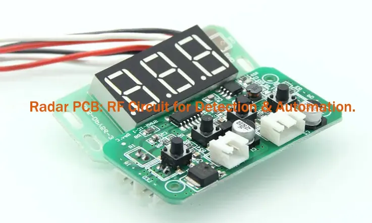
Radar Printed Circuit Boards (PCBs) play a pivotal role in the function of radar systems used for signal detection and processing across various industries. From defense and aerospace to automotive, these specialized boards support the processing of high-frequency RF circuits in environments that require precision. Whether in air traffic control, weather monitoring, or collision avoidance, Radar PCBs ensure the efficient operation of radar systems that depend on accurate signal transmission and reception.
In this article, we explore the process of Radar PCB manufacturing, focusing on the materials, fabrication methods, and design strategies that contribute to high-performance radar solutions. We cover considerations such as RF circuit design, impedance matching, and signal integrity, all of which impact the overall functionality of radar systems.
Introduction to Radar PCB Technology and Its Role in RF Detection Systems
Radar PCBs are central to RF detection systems, driving radar technology that supports operations in defense, aerospace, and automotive sectors. These Radar PCBs are designed to receive, process, and interpret radar signals, allowing systems to function effectively. In fields like military radar, aerospace radar, and automotive radar, Radar PCBs ensure accurate data processing for tracking, navigation, and obstacle detection.
Radar PCBs are designed to handle high-frequency signals, a feature that sets them apart from traditional PCBs. Their design ensures accurate radar signal transmission and reception, while maintaining signal clarity. As Radar PCB technology advances, they become more integrated into systems that support automated detection and real-time analysis. This section delves into why Radar PCBs are fundamental to RF circuit design and detection systems.
What is Radar PCB and Why It’s Essential for RF Detection?
Radar PCBs are specialized printed circuit boards used in radar systems to process and handle RF signals. Unlike standard PCBs, which are focused on general circuit connections, Radar PCBs are specifically engineered to work with the high-frequency signals used in radar systems. The boards are built to manage both the transmission and reception of electromagnetic waves, which allows radar systems to detect and analyze objects.
The design of Radar PCBs must ensure that Radar signal processing is accurate and efficient. These systems rely on the precise handling of radar signals to identify objects and determine their distance, velocity, and direction. Whether deployed in military radar systems to track targets or aerospace radar systems for aircraft navigation, Radar PCBs are responsible for translating radar signals into useful data.
To maintain signal integrity, Radar PCBs are made with high-quality materials that reduce losses and interference, ensuring that radar signals are accurately processed. For example, low-loss dielectric materials help reduce signal attenuation, while impedance matching ensures signals maintain their quality through the entire board.
The Evolution of Radar PCBs in High-Frequency Circuit Design
The development of Radar PCBs has mirrored advancements in radar technology, with a marked shift from analog to digital systems. Early radar systems relied on analog circuitry, which could not process data with the precision needed for modern applications. As radar systems grew more complex, digital signal processing (DSP) was incorporated into Radar PCB designs to enhance their capabilities.
The evolution of Radar PCB design also reflects improvements in high-frequency PCB materials and construction methods. Early radar designs used basic substrates like FR4, but these materials are not suitable for the higher frequencies required in modern radar systems. Newer materials like PTFE (Polytetrafluoroethylene) and ceramic-based substrates offer better performance for high-frequency signal transmission, allowing radar systems to operate at much higher frequencies without losing signal integrity.
As Radar PCB designs have progressed, multilayer PCBs and advanced signal routing techniques have become common. These designs help ensure that high-frequency signals are transmitted with minimal distortion and loss, a must-have for the radar systems used in defense and aerospace sectors. The efficient use of multilayer structures allows for better signal isolation and less interference, making these designs more suitable for high-performance applications.
The Importance of Radar PCBs in Automation and Detection Systems
Radar technology has found its way into automated systems in a variety of industries. In the case of autonomous vehicles, Radar PCBs are tasked with handling radar signals, which are used to detect nearby obstacles, pedestrians, and other vehicles. These systems depend on Radar PCB automation to continuously monitor the surroundings, processing the data to relay information back to the vehicle’s control unit. This allows the vehicle to adjust in real-time, reacting to its environment based on the radar data.
In the defense industry, Radar PCBs are used in surveillance systems to track moving targets, including aircraft, missiles, and ships. The ability to track these targets reliably and continuously is dependent on the Radar PCB design. The use of high-frequency radar boards allows for accurate and continuous monitoring of large areas, which is particularly useful in military defense systems that require real-time tracking and analysis of potential threats.
The capabilities of Radar PCB detection extend to industries like smart cities, where radar is used for monitoring traffic flow, environmental conditions, and public safety. By integrating radar with other sensor technologies, Radar PCBs contribute to improving efficiency and security in urban areas.
Radar PCB Applications Across Industries-
| Industry | Application | Role of Radar PCB |
| Military | Target tracking and surveillance | High-frequency signal processing for target identification and missile guidance systems |
| Aerospace | Weather radar, navigation systems | Ensures accurate weather detection and safe navigation |
| Automotive | Autonomous vehicles, collision avoidance | Provides real-time obstacle detection and lane-keeping systems |
| Smart Cities | Surveillance, traffic monitoring | Monitors and analyzes traffic conditions, enhances public safety |
Types of Radar PCBs and Their Applications
Radar PCBs play a central role in many industries, providing advanced detection capabilities for applications in military, aerospace, automotive, and meteorological systems. Each type of Radar PCB serves a different function and addresses specific requirements. Below, we explore the five primary types of Radar PCBs, providing insights into their unique features and how they serve distinct purposes across various sectors.
Monopulse Radar PCBs
Monopulse Radar PCBs are engineered to use a specific pulse to compare the received signal by utilizing previously recorded signal data. This method helps in determining the precise location of an object in real time, which is especially useful in radar systems requiring continuous tracking of targets.
These PCBs are commonly used in military radar systems, where tracking accuracy is necessary to pinpoint the position of incoming objects, such as missiles or aircraft. The system calculates the position by comparing the pulse’s azimuth and elevation, enabling Monopulse Radar PCBs to be a reliable solution for navigation and surveillance applications.
Features:
●Tracks objects with high precision
●Frequently used in targeting systems for military purposes
●Assists in real-time tracking of aerial objects
Doppler Radar PCBs
Doppler Radar PCBs utilize the Doppler effect, which detects shifts in the frequency of electromagnetic waves reflected from moving objects. By transmitting electromagnetic signals and analyzing how the frequency of the reflected signal changes, Doppler Radar PCBs can assess the speed and velocity of objects within a given range.
In automotive applications, Doppler Radar PCBs are used in systems like adaptive cruise control and collision avoidance. These systems rely on the radar’s ability to measure the speed of nearby vehicles, enabling more precise driving adjustments. By continuously monitoring the speed of surrounding traffic, Doppler Radar PCBs contribute to a smoother and more responsive driving experience.
| Application | Function | Use Case |
| Automotive radar | Measures vehicle velocity | Used in adaptive cruise control systems |
| Aviation systems | Monitors aircraft movements | Air traffic control systems |
| Military surveillance | Detects moving objects and personnel | Employed in tracking systems |
Weather Radar PCBs
Weather radar systems use Radar PCBs to monitor and analyze weather patterns, such as precipitation and wind movements. These systems emit radio frequency signals that bounce off various weather phenomena, like clouds and moisture. The returned signals are then analyzed to determine factors like wind speed and rainfall type.
Weather Radar PCBs are found in meteorological stations, where they contribute to weather forecasting by tracking storm systems and other atmospheric conditions. By distinguishing between different types of precipitation, these Radar PCBs help in issuing accurate weather predictions, particularly in the case of severe storms.
Features:
●Utilizes radio frequency signals to detect atmospheric conditions
●Plays a role in weather prediction and storm detection
●Dual polarization helps identify types of precipitation
Passive Radar PCBs
Passive Radar PCBs work by detecting the signals that are already present in the environment, rather than emitting their own signals. These PCBs capture ambient electromagnetic radiation, such as signals from radio, television, or cellular communications, and analyze how these signals interact with objects in the vicinity.
Passive Radar PCBs are particularly useful in situations where the radar system must remain undetected. This type of radar operates by using signals from other sources, without emitting its own, to detect objects. It has applications in surveillance, border security, and military operations, where the goal is to gather information without giving away the radar system’s location. By blending into the environment, Passive Radar PCBs offer an effective solution for stealth operations, ensuring that potential targets are monitored without alerting them.
Pulsed Radar PCBs
Pulsed Radar PCBs emit high-intensity, high-frequency pulses at a target and wait for the return signal. This technique allows the system to assess the distance to the target, while the Doppler shift method calculates its speed. By using these pulses, Pulsed Radar PCBs can effectively measure distances and detect moving objects.
Pulsed Radar PCBs are frequently used in aircraft radar systems, where they detect and track other airborne objects to prevent collisions. They are also used in weather radar systems for measuring distance and detecting storm systems, where they provide valuable data on the position and velocity of weather events.
| Application | Functionality | Use Case |
| Military surveillance | Detects and tracks moving objects | Tracking systems |
| Weather detection | Measures distance and detects velocity | Used in storm tracking and precipitation detection |
| Aerospace | Detects nearby objects for collision avoidance | Aircraft radar systems |
Key Design Factors in Radar PCB for RF Circuit Integration
When designing Radar PCBs for RF circuit integration, several factors need to be considered to ensure efficient operation. These design factors directly impact how well the Radar PCB integrates into RF detection systems across various industries like military, automotive, and aerospace. This section covers three primary areas of Radar PCB design: impedance matching, material selection, and multilayer PCB stack-up design. Each of these factors plays a role in optimizing the Radar PCB to meet the needs of high-frequency circuits used in radar applications.
By paying close attention to these design factors, Radar PCBs can be engineered to operate smoothly, handling complex RF signals and ensuring that the Radar PCB design remains consistent under high-frequency conditions. The combination of impedance matching, appropriate material choice, and optimized stack-up designs allows Radar PCBs to perform effectively in RF detection systems, improving overall system functionality.
Impedance Matching and Signal Integrity in Radar PCB Design
Impedance matching is a fundamental aspect of Radar PCB design because it ensures that signal integrity is maintained across the PCB. Radar PCBs are designed to handle high-frequency signals that must travel through various layers and components, often under demanding conditions. Without proper impedance matching, signals can be reflected, leading to signal loss, data corruption, or inaccuracies in radar readings.
In Radar PCB signal design, impedance matching ensures that the trace width and materials used for signal transmission align with the specific impedance requirements of the radar system. In RF circuits, even slight mismatches can lead to noticeable signal distortion. To avoid this, design strategies such as utilizing microstrip or stripline structures offer precise control over impedance. This ensures that radar signals flow without interference, providing clear and accurate data transmission. Getting the impedance just right can be the difference between a crisp signal and one that’s all over the place—so it’s all about making sure every bit of the design fits like a glove.
The choice of materials also affects signal integrity. Low-loss materials like PTFE are commonly used in Radar PCBs to ensure minimal signal degradation over long distances or complex pathways. This helps keep radar systems operational with high fidelity, enabling more accurate RF circuit performance in various applications.
Material Selection for Radar PCB Performance in RF Detection
Selecting the right materials for Radar PCB design is integral to ensuring that the board meets the demanding needs of RF detection systems. Radar PCBs require materials that can handle high-frequency signals with minimal interference or loss. Materials such as PTFE, ceramics, and graphene offer unique properties that support the performance of Radar PCBs in RF applications.
PTFE is a widely used material in high-frequency PCBs due to its low dielectric constant and excellent signal retention characteristics. This makes it ideal for Radar PCBs, where signal loss must be minimized. The low-loss nature of PTFE ensures that the radar system operates efficiently, even at higher frequencies.
Ceramic materials are also utilized for their superior thermal conductivity and stability at high frequencies. These materials allow Radar PCBs to function reliably under various environmental conditions, making them suitable for high-power radar systems used in industries like military defense and aerospace.
In recent years, emerging materials such as graphene have shown promise for improving the performance of Radar PCBs. Graphene’s exceptional electrical conductivity and thermal properties provide an advantage in systems where precision and high-frequency signal processing are essential.
Multilayer PCB Stack-Up Design for Radar Circuit Optimization
Multilayer PCB design is a technique commonly used in Radar PCB design to ensure optimal performance for RF circuits. By using multiple layers of materials in the PCB stack-up, we can improve signal integrity, reduce cross-talk, and ensure that high-frequency signals are transmitted with minimal loss.
The multilayer stack-up typically consists of signal layers, ground planes, and power planes that are strategically placed to maintain a clear path for the signals while reducing interference. By separating the different layers, the design minimizes the chances of electromagnetic interference (EMI) and ensures that the radar system can process data more accurately.
One important aspect of Radar PCB stack-up design is the proper use of ground planes. By incorporating dedicated ground layers, we can further isolate the signal traces, preventing external noise from interfering with the radar system’s performance. This layer arrangement also ensures that the radar system can function without disruptions even under high-frequency conditions.
Material Comparison for Radar PCB Applications-
| Material Type | Characteristics | Radar PCB Application |
| PTFE | Low dielectric constant, high-frequency stability | Suitable for aerospace radar and military radar |
| Ceramic Substrates | High thermal conductivity, low loss at high frequencies | Used in high-power radar systems |
| Graphene | Excellent electrical conductivity, strong thermal properties | Emerging use in RF detection systems |
Manufacturing Radar PCBs for Aerospace, Military, and Automotive Radar Systems
The manufacturing of Radar PCBs for applications in aerospace, military, and automotive radar systems requires a specialized approach to meet the demanding operational conditions. These sectors expect Radar PCBs to handle high frequencies and operate reliably in harsh environments. Precision is a hallmark of this manufacturing process, including PCB etching, high-precision fabrication, and testing to ensure the PCB meets the required standards for RF circuits.
In this section, we will explore the fabrication processes, the role of quality control, and advanced manufacturing technologies employed to produce Radar PCBs used in aerospace radar systems, military radar systems, and automotive radar systems. This detailed look will also cover how these technologies help meet specific needs in each industry.
Precision Fabrication and PCB Etching for Radar Circuit Traces
The Radar PCB fabrication process focuses on creating precise RF signal traces that can maintain the integrity of high-frequency signals used in radar detection. PCB etching is a crucial part of this process, where a photosensitive layer is applied to the board, and UV light is used to expose the pattern. This pattern is then etched away to leave the signal traces intact.
Laser drilling is a technique used to form vias that connect the layers of a Radar PCB, ensuring that the signal paths remain uninterrupted. This method helps minimize any potential interference, allowing radar signals to travel accurately. By creating precise vias, laser drilling enables clear connections between layers, ensuring that the radar system functions with minimal signal degradation.
Below is a table that outlines the steps involved in the PCB etching process for Radar PCBs:
| Step | Process Description | Effect on Radar PCB |
| Photosensitive Layer | A light-sensitive layer is applied to define the circuit pattern | Helps to create clear and accurate RF signal routing |
| Exposure to UV Light | The PCB is exposed to UV light, creating the circuit pattern | Ensures precise etching of the signal traces |
| Chemical Etching | The exposed areas are etched away, leaving the circuit traces | Maintains the signal paths and ensures performance |
| Inspection | Manual or automated inspection to verify the etching | Verifies the signal paths remain intact |
These steps help ensure that the Radar PCBs are built with precision, minimizing any potential interference that could affect the radar system’s accuracy.
Quality Control and Reliability Testing for Radar PCBs
Radar PCBs must undergo extensive reliability testing to ensure that they will function as expected in aerospace, military, and automotive radar systems. These tests focus on ensuring that the signal fidelity remains intact and that the RF circuits are not compromised by physical or electrical stress.
Signal fidelity testing is conducted to check the quality and accuracy of the signals transmitted through the Radar PCB. Other tests, like thermal cycling and high-voltage testing, simulate the operational conditions that these Radar PCBs will face in real-world applications.
The table below highlights common reliability tests used for Radar PCBs:
| Test Type | Purpose | Application in Radar PCBs |
| Signal Fidelity Testing | Checks the accuracy and integrity of the transmitted signal | Verifies RF signal transmission and quality |
| Thermal Cycling | Simulates temperature changes and thermal stresses | Ensures Radar PCBs can handle temperature shifts |
| High-Voltage Testing | Tests the PCB’s tolerance to electrical stress | Verifies performance under high electrical loads |
| Mechanical Shock Testing | Assesses the PCB’s ability to withstand physical shocks | Ensures durability under physical stress in automotive radar |
These tests help verify that the Radar PCB can endure the harsh conditions of military radar systems, aerospace radar systems, and automotive radar systems, providing reliable performance over time.
Advanced Manufacturing Technologies for High-Performance Radar PCBs
Radar PCB manufacturing involves the use of advanced technologies that support the production of high-performance RF circuits. Innovations in automated testing, fine-line etching, and multi-layer PCB fabrication allow manufacturers to produce Radar PCBs that meet the demands of high-frequency, high-speed radar systems.
One technology is automated optical inspection (AOI), which allows manufacturers to inspect Radar PCBs for defects at each stage of the production process. This helps identify potential issues with signal routing, component placement, and overall PCB quality. Fine-line etching is another advancement that enables the creation of more intricate and accurate signal traces, reducing the chance of signal interference.
Here’s a table summarizing some of the manufacturing technologies used in Radar PCB production:
| Technology | Purpose | Effect on Radar PCB |
| Automated Optical Inspection (AOI) | Uses cameras to inspect Radar PCBs for defects | Detects issues with signal traces and component placement |
| Fine-Line Etching | Enables more precise etching of signal traces | Minimizes signal loss and interference |
| Multi-Layer PCB Design | Stacks multiple layers to enhance performance | Allows for more compact and complex Radar PCBs |
| Laser Drilling | Creates precise vias between PCB layers | Improves signal routing and RF circuit performance |
These advanced manufacturing techniques ensure that the Radar PCBs can meet the high-performance requirements of aerospace, military, and automotive radar systems, supporting reliable operation even under extreme conditions.
How Optimizing Radar PCB Performance in Harsh Environments?
Radar PCBs used in military, aerospace, and automotive radar systems often operate under extreme conditions that challenge their reliability. From high-frequency signals to intense temperature changes, Radar PCBs must maintain performance and ensure consistent signal transmission. This section explores how to tackle challenges such as signal loss, thermal management, and shielding to maximize Radar PCB efficiency and longevity.
Minimizing Signal Loss and Ensuring High-Quality Radar Signals
In Radar PCB design, one major challenge is minimizing signal loss while maintaining high-quality radar signals, especially for precision applications like military radar systems. Signal loss can stem from factors like trace resistance, poor impedance matching, and interference from external sources. To keep RF signal integrity intact, even over long distances and in tough environments, we can employ specific design strategies that ensure the signals remain clean and strong. Using advanced routing techniques, impedance control, and effective shielding can help mitigate these issues, allowing radar systems to operate efficiently and without disruption.
Impedance matching is an effective way to reduce signal loss. Ensuring that the impedance of the signal traces aligns with that of the components helps minimize reflections, which would otherwise degrade the signal. This is a standard practice in high-frequency signal transmission to prevent signal degradation.
Another method is selecting low-loss materials for the PCB, such as PTFE or ceramic materials. These materials offer low attenuation at high frequencies, enabling the radar signals to travel without significant degradation.
Here’s a table that compares the signal loss characteristics of different materials:
| Material | Dielectric Constant (Dk) | Signal Loss (dB/cm) | Use in Radar PCBs |
| PTFE | 2.2 | 0.004 | Ideal for high-frequency RF circuits |
| Ceramics | 3.5 | 0.007 | Common in military and aerospace |
| FR-4 | 4.5 | 0.010 | Often used for low-frequency designs |
By using low-loss materials and implementing impedance matching, Radar PCBs can ensure that signal integrity is maintained across a range of environments, delivering reliable RF signals for radar detection.
Thermal Management Solutions for Radar PCB Efficiency
One of the hurdles Radar PCBs face in tough environments is managing heat dissipation. High-frequency circuits tend to produce a fair amount of heat, and without proper thermal control, components risk overheating, which can disrupt PCB performance. To keep things running smoothly, effective thermal management is a must. This includes employing techniques like heat sinks, thermal vias, and carefully chosen materials to ensure the PCB doesn’t suffer from heat buildup. When designed well, these strategies keep the radar system performing at its best, even under intense conditions, ensuring longevity and reliability.
One common solution is the use of heat sinks to draw heat away from key areas of the PCB. Graphene and ceramic composites, with their high thermal conductivity, are often used in high-frequency PCBs for thermal management. These materials dissipate heat more effectively and prevent overheating.
Additionally, PCB layout optimization can help by placing heat-sensitive components away from heat-generating areas. This reduces the thermal stress on individual components and ensures consistent performance.
The following table shows the thermal conductivity of materials used in Radar PCB fabrication:
| Material | Thermal Conductivity (W/m·K) | Usage | Effectiveness in Radar PCBs |
| Graphene | 500 | High-performance cooling | Outstanding heat dissipation for high-frequency applications |
| Ceramic Composites | 150 | Military and aerospace | Effective at dissipating heat in harsh conditions |
| Copper | 400 | Common in heat sinks | Common choice for general thermal management |
By incorporating these thermal management solutions, Radar PCBs can operate reliably in high-temperature environments and avoid performance degradation caused by excessive heat.
Shielding and EMI Protection for Radar PCBs
Electromagnetic interference (EMI) is another challenge faced by Radar PCBs, especially in systems used in military radar applications, where even the smallest interference can disrupt signal accuracy. EMI shielding is an essential part of Radar PCB design, preventing unwanted signals from affecting the PCB’s operation.
EMI shielding involves using materials like copper, aluminum, and mu-metal to block interference. These materials can be integrated into the PCB itself or used in external enclosures to protect against external sources of electromagnetic noise. Faraday cages are often used in military and aerospace radar systems to ensure that the Radar PCB remains unaffected by external electrical fields.
In high-frequency radar applications, applying PCB trace shielding to signal paths is a practical way to keep interference at bay. This shielding helps protect radar signals from outside disturbances that could mess with the clarity and accuracy of the data. It’s especially useful in scenarios where signal precision is a must, like in defense or aerospace systems.
Here’s a comparison table for different shielding materials used in Radar PCB design:
| Material | Shielding Effectiveness (dB) | Application |
| Copper | 60-80 dB | Used for general shielding |
| Aluminum | 40-60 dB | Common in automotive radar systems |
| Mu-Metal | 80-100 dB | High-end shielding for military radar |
By applying EMI shielding materials and techniques, Radar PCBs can operate with minimal interference, maintaining the clarity of radar signals even in electrically noisy environments.
How to Choose the Right Radar PCB Manufacturer?
Selecting the right manufacturer for your radar PCB is not just about finding someone who can make a product. It’s about finding a partner who understands the complexity of radar systems and can deliver quality, precision, and reliability. Here are the factors to keep in mind when making your choice:
1. Experience in Radar PCB Design and Manufacturing
Radar systems present unique challenges. When selecting a manufacturer, prioritize those with extensive experience in designing and producing radar PCBs. They should be well-versed in high-frequency applications, maintaining signal integrity, and ensuring proper impedance matching—core aspects for radar functionality. For instance, a manufacturer experienced with military or aerospace radar systems is likely to be more familiar with the reliability standards and environmental conditions these systems require.
2. Expertise in Handling Specialized Materials and Design
Radar PCBs often require specific materials and design techniques. Whether it’s working with specialized substrates like Teflon or managing controlled impedance routing, the manufacturer should have a team of engineers who are proficient in the latest radar PCB technologies. You want a partner who can guide you through the design process, offering insights on the best materials, fabrication methods, and thermal management strategies.
3. Stringent Quality Control Practices
With radar technology, reliability is non-negotiable. Any defect in the PCB could impact the performance of the entire radar system. Ensure that the manufacturer has a robust quality control process in place, including testing for signal integrity, impedance matching, and component durability. You should request details on their quality assurance protocols and past performance, especially if they have successfully passed industry-standard tests for radar systems.
4. Advanced Manufacturing Capabilities
Radar PCB manufacturing isn’t a simple process. The manufacturer needs the equipment to handle high-frequency circuits and multilayer PCB designs. Ensure that the manufacturer has the capacity to handle complex designs, including high-density interconnects (HDI), microvia drilling, and thermal management. In particular, look for the ability to process advanced signal routing techniques and manage the intricate challenges that come with high-frequency radar signals.
5. Competitive Pricing and Timely Delivery
While pricing should never be the sole deciding factor, it’s important to evaluate whether the cost aligns with the quality and lead times you’re expecting. Get multiple quotes, but don’t fall for the cheapest option if it compromises quality or delivery timelines. Keep in mind that radar systems often require tight deadlines, especially for industries like defense, aerospace, or automotive, where delays can lead to substantial setbacks.
6. Strong Customer Support and Communication
Your relationship with the manufacturer doesn’t end once the order is placed. A reliable manufacturer will offer strong customer support throughout the entire process, from design assistance to post-production services. Look for a team that is communicative, responsive, and willing to make adjustments when needed. If something goes wrong, you need to know that the manufacturer will have your back.
7. Proven Track Record in Your Industry
Depending on your application—be it military, automotive, or industrial—you need a manufacturer that understands the specific needs of your sector. For instance, if you’re designing a radar system for autonomous vehicles, you’ll want a manufacturer with experience in automotive-grade components and testing. Ask for case studies, industry certifications, or previous customer testimonials that demonstrate their ability to handle your type of radar PCB.
Why Choose Us?
China Cutting-edge Radar PCB Circuit Boards Manufacturer – JarnisTech!
When it comes to Radar PCB manufacturing, JarnisTech stands out for its ability to combine expertise, innovation, and a customer-centric approach to every project. With more than two decades of experience in the industry, we specialize in the manufacturing of high-performance radar PCBs tailored to meet the needs of demanding applications in industries such as military, aerospace, automotive, and weather monitoring systems.
Our team of experts, with specialized knowledge in the production of Radar PCB materials and advanced RF circuit designs, works tirelessly to ensure that every radar circuit we produce is not only precise but also capable of performing at optimal levels in challenging environments.
1.Industry-Leading Expertise and Advanced Technology
At JarnisTech, we leverage cutting-edge technology to manufacture Radar PCBs that perform under extreme conditions, from aerospace radars that monitor air traffic to automotive radar systems used in collision avoidance technologies. Our ability to consistently innovate and apply advanced manufacturing techniques sets us apart from others in the field.
We understand that Radar PCB design requires an intricate balance of signal integrity, precise impedance matching, and reliable thermal management. That’s why we use high-grade materials, including low-loss dielectric materials and PTFE, to ensure that each board can withstand high frequencies without compromising on performance.
| Manufacturing Technique | Benefit | Application |
| Laser Drilling | Ensures high precision and clean trace edges | For high-frequency radar circuits |
| Advanced Etching | Guarantees sharp and clear signal paths | For signal integrity in RF detection systems |
| Multilayer PCB Stack-Ups | Maximizes space and performance | For high-speed radar systems and automotive radars |
2.Tailored Radar PCB Solutions for Diverse Applications
We know that radar PCB applications vary significantly from one sector to the next. Military radar systems require enhanced durability and precision, while weather radar systems demand high sensitivity and fast data processing. At JarnisTech, we specialize in creating customized radar PCB solutions to meet the unique needs of each project.
Whether you’re developing a Doppler radar PCB for velocity detection in an automotive system or a Monopulse radar PCB for tracking aircraft in defense applications, we have the expertise to deliver tailored solutions. We work closely with our clients to ensure that every Radar PCB aligns with their specific requirements, whether it’s for aerospace radar, weather monitoring systems, or automotive radar systems.
3.Precision Fabrication and Reliability Testing
Radar PCBs are often used in environments where precision, reliability, and performance are non-negotiable. At JarnisTech, we have perfected the art of precision PCB fabrication, incorporating signal fidelity testing and comprehensive reliability assessments throughout the manufacturing process.
Our multi-step quality control procedures ensure that all Radar PCBs meet the required standards for industries with demanding operational conditions, like military radar or aerospace applications. We conduct rigorous tests to check for signal integrity and thermal management efficiency, ensuring that our boards maintain optimal performance even under extreme operating conditions.
| Test Type | Purpose | Application |
| Signal Fidelity Testing | Confirms the accuracy of signal transmission | Military radar systems, automotive radar |
| Thermal Performance Test | Verifies heat dissipation capabilities | Aerospace radar, weather radar systems |
| Environmental Stress Test | Ensures radar PCB durability under stress conditions | Military and aviation environments |
4.Advanced Manufacturing Processes for Optimal Radar PCB Performance
The complexity of high-frequency radar circuit design requires specialized manufacturing processes. JarnisTech is at the forefront of adopting automated manufacturing technologies that streamline production while maintaining the highest standards of Radar PCB performance.
From multilayer PCB designs that improve space efficiency to high-performance etching processes that enhance signal clarity, we make sure that every Radar PCB is crafted to perform under the most demanding conditions. Our automated testing systems ensure each board is tested for signal loss, impedance matching, and thermal stability, making sure that our Radar PCBs continue to provide exceptional results in real-world applications.
| Technology | Benefit | Radar PCB Application |
| Automated Testing | Maximizes accuracy in quality control | Used in aerospace, military, and automotive |
| Laser Precision Etching | Enhances signal clarity and precision | For RF signal processing and high-frequency circuits |
| Multilayer Design | Optimizes space and performance | Ideal for space-saving applications in weather radar |
5.Commitment to Customer Satisfaction and Long-Term Partnerships
At JarnisTech, we recognize that successful partnerships are built on trust and collaboration. Our customer-first approach ensures that your unique requirements are met at every stage of the project. From Radar PCB design to production, we are committed to delivering quality and reliable solutions that align with your timelines and specifications.
Why Partner with JarnisTech?
With two decades of experience, JarnisTech is more than capable of providing Radar PCB manufacturing services that cover everything from design to final delivery. If you’re looking for a partner that understands the nuances of high-frequency circuit design, signal processing, and RF detection systems, look no further than JarnisTech.
FAQs & Radar PCB:
1. How do Radar PCBs reduce signal interference?
Through shielding and proper grounding techniques.
2. How are Radar PCBs different from standard RF PCBs?
Radar PCBs handle higher frequencies and complex data processing.
3. Are certifications required for Radar PCB manufacturing?
Yes, especially for aerospace and defense, like ISO 9001 or AS9100.
4. Why is impedance matching important in Radar PCBs?
It ensures consistent signal performance and minimizes loss.
5. How does thermal management affect Radar PCB performance?
It prevents overheating and ensures stable operation during high-frequency use.