The data output of the CAD tool, specifically in the ODB++ format, remains significant even when the PCB design is deemed sound and thoroughly described. The formatting and organization of the design data play a crucial role in facilitating the manufacturer’s understanding and interpretation of the intended construction. Despite the availability of other file formats like Gerbers (accompanied by a drill file, netlist, BOM, board drawing, and readme text) or IPC-2581, a substantial majority of fabrication and assembly orders, approximately 90% in our company’s case, still rely on the Gerber-based approach. It is worth noting that ODB++ was introduced over 15 years ago by Valor as an intelligent means of describing designs at the manufacturing level.
Each zipped ODB++ file, when comprehensive, consolidates all the essential information necessary for the manufacturing and assembly of a printed circuit board. The advantage lies in its direct compatibility with the front-end CAM system, enabling seamless loading and utilization by the manufacturer. Therefore, the ODB++ format, with its inclusive nature and direct integration capabilities, remains a pertinent consideration for ensuring successful interpretation and execution of the design by the manufacturer.
What is ODB++?
ODB++ is a proprietary CAD-to-CAM data exchange format specifically developed for electronic device design and manufacturing processes. Its primary objective is to facilitate the seamless transfer of design information across various tools and systems utilized in the electronic device industry. ODB++ employs an ASCII format to store its data, organized into distinct folders and files, thereby enabling machine-readability and direct interpretation by proficient users. This format superseded the previous reliance on binary database files, which was necessitated by the limited storage capacity of hard drives. However, with the substantial advancements in hard drive capabilities, ODB++ emerged as a more efficient alternative.
The key advantages offered by ODB++ encompass enhanced speed, precision, and automation. PCB manufacturing greatly benefits from ODB++ files as they effectively minimize errors during the production process. Furthermore, they significantly expedite operations by seamlessly integrating with CAM front-end systems to generate precise device commands for manufacturing processes.
Additionally, ODB++ enables manufacturers to make minor design modifications in collaboration with their customers while ensuring the integrity of the original design. These alterations are meticulously compared to the netlist to guarantee their accuracy.
Overall, ODB++ stands as a proprietary CAD-to-CAM data exchange format dedicated to facilitating the efficient transfer of design data within electronic device design and manufacturing. It serves as a reliable conduit for seamlessly exchanging information between design and manufacturing stages, as well as between different EDA/ECAD suppliers.
ODB++ Files Family
The ODB++ file format has been enhanced to optimize PCB design and manufacturing workflows. The complete package is now called the ODB++ family, which contains the following extensions:
ODB++ Design – Contains the primary PCB design data generated by EDA tools. This provides the foundation for conducting design for assembly (DFA), design for manufacturing (DFM), and related analyses.
ODB++ Process – Converts the ODB++ design data into machine-readable formats that can be ingested by production equipment. Enables automated data exchange between design tools and fabrication machinery.
ODB++ Manufacturing – An advanced version of ODB++ Process files tailored for manufacturing floor operations. Facilitates communication between smart factory software and production equipment. Allows manufacturing data to flow seamlessly from design tools to the shop floor.
In a words, the ODB++ family of formats connects PCB design to manufacturing through standardized, machine-readable data exchange. The extensions enable optimized workflows for fabrication, assembly, test, and other manufacturing activities.
ODB++ File Structure
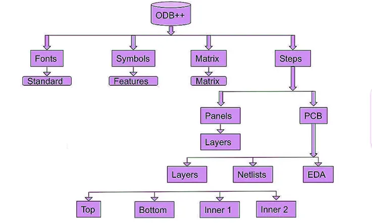
The ODB++ data, despite being presented as a single file, is actually structured as a framework comprising a collection of directory files that are compressed using the gzip algorithm. This arrangement forms a standardized file system structure, enabling effective organization and management of the data.
A notable advantage of the ODB++ format is that all the files contained within it are in ASCII format, making them easily readable by advanced users without the need for specialized extraction software. This accessibility enhances the convenience and flexibility of working with ODB++ files.
In the past, many legacy systems relied on binary database files, necessitating the use of specific format conversion tools. Vendors preferred these databases due to limitations in disk space. However, with the significant advancements in hard disk capacity, the preference has shifted towards more versatile formats like ODB++.
Furthermore, the emergence of efficient compression techniques has further improved the ODB++ format. Large files within ODB++ are stored in the standard UNIX compress format, allowing for effective reduction in file size while maintaining their ASCII readability.
Overall, the ODB++ format’s utilization of an ASCII-readable file structure, along with its compatibility with modern storage capacities and compression techniques, contributes to its efficiency and convenience in the electronic device design and manufacturing domain.
ODB++ Format Advantages
The ODB++ format, based on the IPC 2581 standard, offers an open and freely accessible file format for the integration of new technologies. It enjoys support from a wide range of CAD and CAM software, making it widely compatible and easily adopted. The standardization and open nature of the format contribute to its widespread use. It was officially approved by the Printed Circuit Society in 2008.
While not as widely adopted as Gerber, ODB++ is a reliable file format with many advantages. It shares similarities with Gerber, including a standardized file structure and the ability to perform quality checks. ODB++ also provides features such as the ability to merge connected netlists, panel data, and specific layer stacks. Additionally, it offers robust security measures. Despite these advantages, ODB++ files may not always enjoy the same level of popularity among engineers and manufacturers as Gerber files.
ODB++ files encompass essential design information for the product. Depending on the configuration of CAD tools and Design for Manufacturability (DFM) tools, ODB++ files can also carry additional data such as network names, inner layer information, and component details. Leveraging these features can significantly enhance manufacturing processes.
ODB++ is particularly well-suited for third-party software integration. Its broad support in CAD tools enables users to generate files tailored to specific models or requirements. The open-source nature of the ODB++ database allows for the creation of ODB++ files using various CAD tools, promoting flexibility and interoperability.
ODB++ Vs Gerber Standard
The ODB++ and Gerber standards are widely recognized as the two most popular and efficient PCB design standards in the industry. The ODB++ standard employs a hierarchical structure to store and organize important design information, which is then compressed into a single file. Compared to the Gerber format, the ODB++ file format is notably easier to comprehend.
The comprehensive structure of the ODB++ file minimizes the chances of human or machine errors during data transfer, thereby reducing the risk of inaccuracies. Additionally, the ODB++ format facilitates faster analysis, as CAM systems find it easier to examine ODB++ design data compared to Gerber files.
In terms of data inclusion, ODB++ has an advantage over Gerber as it can encompass a substantial amount of information, including drill files. On the other hand, Gerber files lack the capability to incorporate drill files. Consequently, the ODB++ standard proves to be more efficient and preferred by PCB fabricators due to its ability to consolidate a vast amount of data into a single file.
The ODB++ file can encompass diverse information simultaneously, such as material stack-up, placement data, and bill of materials (BOM). In contrast, the Gerber standard offers the advantage of easy sharing via email due to its portability, enabling seamless transfer through email communication.
The Gerber standard’s output is highly automated, resulting in minimal issues related to debugging and data presentation. When comparing ODB++ and Gerber, it becomes evident that the ODB++ standard complements some of the weaknesses inherent in the Gerber standard.
As a result, the ODB++ standard stands out for its efficient data organization, reduced risk of errors, faster analysis, and ability to encompass comprehensive design information, making it a preferred choice among PCB fabricators.
Data obtained from ODB++ files
Manufacturers often collaborate with customers to make minor adjustments in order to maintain the integrity of designs. If there are issues such as insufficient spacing or inadequate pad size, the Valor system promptly identifies them, allowing for easy resolution through minor edits. Moreover, the system automatically verifies these edits against the netlist, ensuring that the changes do not have any unintended consequences elsewhere in the design.
In the case of ODB++ files, each zipped file contains all the necessary information for the successful manufacturing of a printed circuit board. This comprehensive data can be directly loaded into the front-end CAM system, enabling efficient generation of programs to drive the various process equipment. Conversely, when designs are received in the form of Gerbers and accompanying files, additional time is required to convert these files for review within our system. This highlights the preference of quick-turn manufacturers for production formats that streamline the transfer of designs to the fabrication stage, allowing for more efficient and timely processing.
What is the ODB++ Viewer?
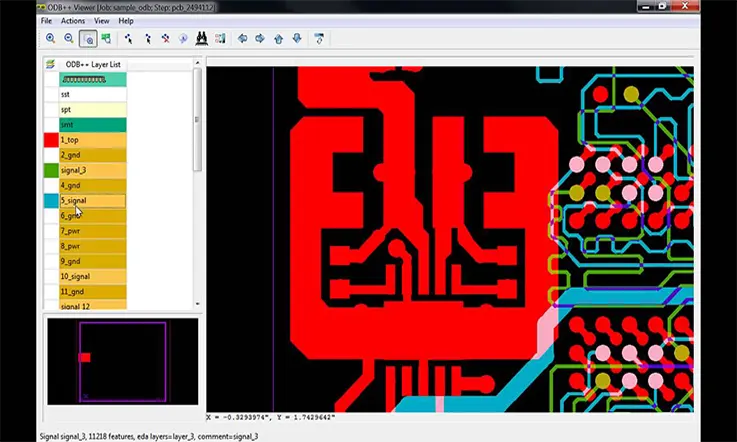
The ODB++ viewer is a valuable tool that allows PCB designers to effectively review and analyze the data provided by PCB manufacturers for equipment programming and analysis purposes. It also serves as an excellent tool for incoming inspection. With the ODB++ viewer, designers can conveniently review their PCB product models from anywhere in the world. Being a free program, the ODB++ viewer offers a wide range of features and benefits.
The online ODB++ viewer facilitates the viewing of PCB engineering graphics and allows for the importation of CAD data. You can easily download and install the ODB++ viewer online. Its widespread support within the electronics supply chain has contributed to its popularity. The availability of this program for free and online ensures that PCB designers can easily gain access to it and incorporate it into their workflows as needed.
ODB++ files contain crucial design information that significantly enhances efficiency for PCB manufacturers. The main formats commonly used today are ODB++ Design, ODB++ Process, and ODB++ Manufacturing. When these files are merged, it becomes possible to create a unified data structure that represents the entire PCB, providing a comprehensive view of the design.
Overall, the ODB++ viewer plays a pivotal role in facilitating effective communication and collaboration between PCB designers and manufacturers. Its accessibility, feature-rich nature, and ability to handle ODB++ files make it an indispensable tool in the electronics industry.
ODB++:Importance of CAD and CAM in PCB Fabrication
The printed circuit board (PCB) fabrication process begins with computer-aided design (CAD) software, which enables virtual modeling of the PCB layout. CAD tools provide critical functionality beyond just design, including design reuse, auto-routing, 3D visualization, and data management.
Once the PCB design is finalized and verified, it moves to computer-aided manufacturing (CAM) software for physical realization. The role of the CAM system is to translate the virtual CAD design into a manufactured product.
Lack of a uniform data exchange protocol between disparate CAD and CAM tools previously created integration challenges. To address this, several CAD-CAM data exchange formats were developed as bridges between incompatible tools. One such solution is the ODB++ format, which serves as a standardized data exchange conduit enabling seamless CAD-CAM workflows.
In summary, ODB++ and similar CAD-CAM transfer protocols allow PCB designs to smoothly transition from virtual concept to physical product by facilitating interoperability between design and manufacturing environments.
Wrap Up
The ODB++ format signifies a significant advancement over traditional formats in facilitating data exchange between PCB designers and manufacturers. This modern approach offers numerous benefits, including enhanced quality, improved production efficiency, reduced assembly times, and faster time to market. As a result, an increasing number of designers are being drawn to adopt the ODB++ format.
The widespread adoption of the ODB++ standard is evident, with support now available from virtually all PCB design system manufacturers. This broad support ensures compatibility and seamless integration of ODB++ within the design workflow, further contributing to its popularity among designers and manufacturers.
By embracing the ODB++ format, designers can leverage its advantages to achieve higher quality PCB production, streamline manufacturing processes, minimize assembly times, and ultimately accelerate the time to market for their products. The format’s ability to provide a comprehensive representation of the PCB design and manufacturing data fosters effective collaboration and enables efficient communication between designers and manufacturers.
Overall, the ODB++ format has emerged as a preferred choice for data exchange in the PCB design industry due to its ability to drive improvements at various stages of the production cycle, ultimately leading to enhanced product quality, optimized manufacturing, and faster time to market.
Related Posts:
1. Gerber Files: How to Generate in PCB Design Process?
2. Gerber Files: Role in PCB Manufacturing
4. Critical Information about Gerber Files for PCB Manufacturing
5. PCB Bill of Materials: A Comprehensive Guide to Effective Documentation