
As a PCB design engineer, it’s essential to navigate through the various standards related to PCB Design. Regardless of the industry you work in, whether it’s electronics, healthcare, or manufacturing, it’s easy to feel overwhelmed by the array of standards available. However, it’s crucial to select an electrical contract manufacturer that adheres to the IPC requirements for PCB design to ensure optimal results.
Established in 1957, the IPC – Association Linking Electronics Industries, maintains the most widely recognized quality and reliability standards for PCB design. IPC standards cover everything from the materials used in designing rigid and flexible boards to the manufacturing processes. Therefore, it’s vital to evaluate your electronic contract manufacturer’s experience and adherence to IPC industry standards to guarantee the dependability and quality of your next PCB board design.
IPC Standards: What are them?
As a PCB Manufacturer, it’s important to understand that the IPC standards were established primarily to serve the electronic manufacturing industry. These standards are typically issued by a trade organization known as the IPC. Initially, while the IPC was being established, its main focus was serving as an institute for printed circuits, but it later repurposed itself to help with the packaging and interconnection of electrical circuits.
Furthermore, the IPC standards provide a foundation for the electronic industry’s performance specifications, inspection requirements, performance standards, assembly, design, and interconnections. These guidelines are widely followed across the world and have become an industry benchmark for PCB design and manufacturing.
One of these standards is the IPC-2220 Series, which covers the general requirements for printed board design, as well as specific requirements for various types of PCBs, including rigid and flexible boards, and high-density interconnect (HDI) boards. Adhering to these standards can help ensure that the PCBs are designed and manufactured to meet the functional requirements while being produced efficiently and effectively, eventually leading to higher quality, reliability, and cost-effectiveness in the final product.
Overview of IPC-2220 Family of Standards
The IPC-2220 family of standards is a set of guidelines and requirements related to the design of printed circuit boards (PCBs). The family includes several standards, such as IPC-2221, IPC-2222, IPC-2223, IPC-2224, and IPC-2225, that provide specific requirements and recommendations for different types of PCBs, from single-sided to high-density interconnect (HDI) boards.
IPC-2220 standards cover topics such as design constraints, layer stacking, board dimensions, materials selection, surface finishes, and high-speed design considerations. These standards also provide guidelines for creating PCB designs that can be manufactured efficiently, effectively, and economically while meeting the functional requirements of the application.
The IPC-2220 family of standards serves as a valuable resource for PCB designers, manufacturers, and assemblers, ensuring that the boards meet quality and reliability requirements. By following these standards, designers can create PCBs that not only meet performance and reliability requirements but also can be more easily produced and assembled, reducing costs and improving overall product quality.
Importance of Complying with PCB Design Standards
Compliance with PCB design standards is crucial for the following reasons:
● Quality Assurance: Adhering to PCB design standards ensures that the final product meets industry requirements, reducing the risk of errors or malfunctions.
● Cost-effectiveness: Following established standards allows for consistent and efficient production processes, preventing errors and costly design revisions.
● Compatibility: Design standards ensure that PCBs are compatible with other components and systems, promoting seamless integration and overall success.
● Safety: Standards also consider safety measures, reducing the risk of electrical hazards, fires, or other safety concerns.
● Industry recognition: Complying with PCB design standards allows companies to demonstrate their commitment to quality and adherence to industry practices, instilling confidence in their products and services in the eyes of prospective customers.
So, compliance with PCB design standards is essential for ensuring quality, reducing costs, promoting compatibility and safety, and gaining industry recognition and trust.
IPC 2220 Series: Family Of Design Documents
The IPC-2220 Series of standards is based on the IPC-2221 Generic Standard on Printed Board Design. This standard serves as the foundational document that outlines the basic requirements for designing printed boards, regardless of the materials used.
Once these foundational requirements have been established using IPC-2221, the designer can then determine which sectional standard is most appropriate for the specific technology being utilized. These sectional standards, such as IPC-2222 for rigid organic PCBs or IPC-2223 for flexible PCBs, provide specific guidelines for designing and manufacturing various types of PCBs. By following these sectional standards, designers can ensure that their PCBs are designed and manufactured with precision, meeting the necessary industry requirements to create high-quality, reliable final products.
Six sectional standards are included with the series:
● IPC-2222: Rigid Organic Printed Boards Sectional Design Standard
● IPC-2223: Flexible Printed Boards Sectional Design Standard.
● IPC-2224: Sectional Standard for Design of PWBsfor PC Cards.
● IPC-2225: Organic Multichip Modules (MCM-L) and MCM-L Assemblies Sectional Design Standard.
● IPC-2226: Sectional Design Standard for High Density Interconnect (HDI) Printed Boards.
● IPC-2227: Sectional Design Standard for Embedded Passive Printed Board Embedded Passives.
Note: At this time, we are not going to discuss the IPC-2227 standard.
What Is the IPC-2221 Standard?
The IPC-2221 standard is widely recognized as a hallmark of quality in the electronics industry, providing essential definitions for a range of elements involved in PCB design. These definitions are significant in establishing design requirements for materials such as plating and substrates, testability, thermal management, thermal reliefs, and annular rings, among others.
However, specific design standards may be more precise than the principles they replace, leading to some design guidelines becoming obsolete. For example, the IPC-6018 and IPC-6012 each provide design criteria for high-frequency and robust boards, and these supplemental requirements must be consistent with the standards established by IPC-2221 for generic PCBs.
It’s important to note that despite its value in providing design requirements, the IPC-2221 standard is not used to evaluate manufacturing flaws, yield, and product reliability. For rigid boards, either the IPC-A-600 or the IPC-6012 standards are utilized in validating the manufacturing process of rigid PCBs.
In designing PCBs, each variety of board is measured against a unique set of criteria. The design requirements of IPC-2221 and IPC-2222, for example, must be followed when designing rigid PCBs. The same applies to flex, HDI (high-density interconnect), and multichip modules. Consequently, manufacturers must ensure that IPC-2221 generic standards are used according to comprehensive requirements tailored for specific circuit boards.
PCB designers should be mindful of striking a balance between a board’s thermal, mechanical, and electrical properties while considering manufacturing obstacles, reliability, and cost. The IPC-2221 standard is helpful in bringing attention to these relevant aspects, as well as covering various other topics connected to board design.
IPC-2221 Documentation Hierarchy
The IPC-2221 standard is a fundamental document for physical design principles in printed board technology. It is supplemented by a range of subsection documents that provide detailed and specialized information on specific areas of PCB technology. This list is a brief summary and is not considered a fundamental part of the generic standard. These documents are collectively identified as the PCB Design Document Set known as IPC-2220-FAM.
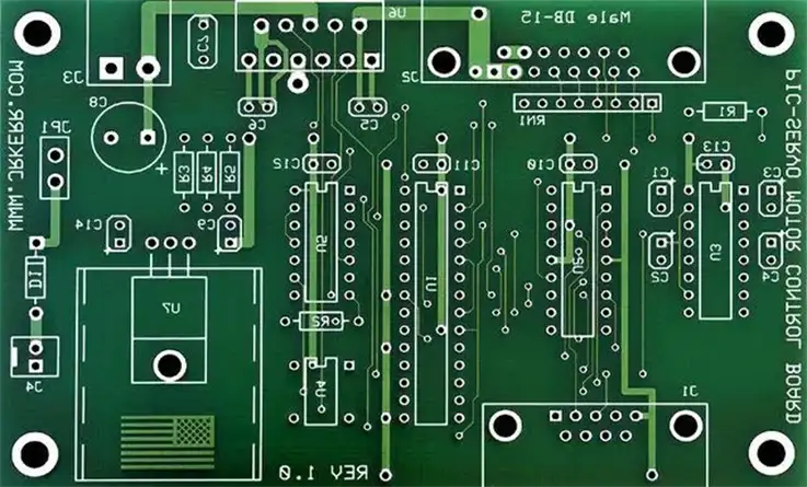
IPC-2222: Rigid Organic Printed Boards Sectional Design Standard
Achieving a flawless printed circuit board (PCB) design requires adherence to IPC-2221 guidelines, which prescribe optimal principles for efficient component placement, routing density, and superior electrical performance. Furthermore, in concert with IPC-2221, IPC-2222 specifications are established to enhance the manufacturability of rigid circuits, with the following criteria being of particular significance:
● Dielectric spacing
● Routing parameters.
● Selection of materials.
● Mechanical parameters.
● Board thickness tolerance.
● Holes and interconnections specifics.
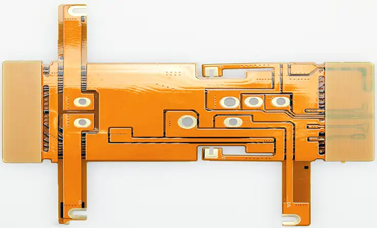
IPC-2223: Flexible Printed Boards Sectional Design Standard
IPC-2223 is a standard that defines specific design guidelines for Flexible Printed Boards (Flex PCBs) and component mounting and interconnection structures, in conjunction with IPC-2221. Flex PCBs are constructed using insulating sheets, reinforced or unreinforced dielectric, and metallic components. The following key concepts of IPC-2223 are crucial for designing Flex PCBs:
● Selective (Button) Plating.
● Copper Filled Vias/Microvias.
● Material Selection and Construction.
● Impedance and Capacitance Control.
● Unsupported Edge Conductors/Fingers.
● Minimum Bending for Flexible Circuits with Coverlay.
IPC-2224: Sectional Standard for Design of PWBs for PC Cards
IPC-2224 establishes requirements for designing printed circuit boards used in computer card-type components. The materials used in these PCBs may be standardized, reinforced, or a combination of natural and non-natural items, with single-sided, double-sided, or multilayered affiliations. The aims of the requirements are to develop design strategies and recommendations that will be used in conjunction with IPC-2221 to create detailed layouts for placing and connecting active and passive components. These components may be through-hole, surface mounting, fine pitch, ultra-fine pitch, array mounting, or unpackaged bare die.
The PCB materials used may be combinations that can perform physical, thermal, environmental, and digital functions. The following types of PCB boards are some examples:
● Single-sided PCB Board.
● Double-sided PCB Board.
● Multilayer Board without Blind or Hidden Vias.
● Multilayer Board with Blind or Hidden Vias.
● Multilayer Steel Core Board without Blind or Hidden Vias.
● Multilayer Steel Core Board with Blind or Hidden Vias.
IPC-2225: Organic Multichip Modules (MCM-L) and MCM-L Assemblies Sectional Design Standard
IPC-2225 is a standard that sets forth requirements, considerations, and guidelines for designing organic mounting structures that interconnect chip components used in various applications. These organic mounting structures combine to create finished functional Single Chip Module (SCM-L), Multi-Chip Module (MCM), or MCM-L assemblies. The standard extensively provides information regarding thermal, electrical, electromechanical, and mechanical parameters that require attention while designing these structures.
Key concepts in IPC-2225 include the properties of microvia materials, conventional die attach materials, and adhesive interconnections. PCB designers need to take these considerations into account to ensure effective organic mounting structures that can support reliable interconnections between chip components..
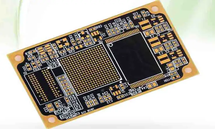
IPC-2226: HDI Printed Board Sectional Design Standard
IPC-2226 is a standard that sets forth requirements and considerations for the design of high-density interconnect (HDI) printed boards and structures, both natural and non-natural, for component placement and interconnections. The standard aims to generate design concepts and recommendations that will be used in conjunction with the comprehensive requirements of IPC-2221.
In cases where the requirements of IPC-2226 intersect with the requirements of other section documents (such as IPC-222, IPC-2223, and IPC-2225) that define the core material properties, those features will become an obligatory element of this standard.
IPC-2226 provides guidelines for signal, power, ground, and mixed signal layers, dielectric separation, expansion and metallization requirements, and other key design features for HDI substrates. These guidelines help ensure that HDI substrates provide reliable and high-performing interconnects suitable for various electronics applications.
In the production of printed circuit boards (PCBs), it is recommended to use a High-Density Interconnect (HDI) configuration when the pitch between Ball Grid Array (BGA) terminals is less than 0.35 mm or 0.25 mm. Typically, in BGA design, mini traces, Via In Pad (VIP), micro vias, blind vias, or other microtia techniques, built-up laminations, and high-speed performance issues need to be considered. In order to create microvias, the prepreg material needs to be thinned to a minimum thickness of 2 mil (0.05 mm). These techniques and configurations allow for more efficient use of board space, improved signal performance, and reduced electromagnetic interference.
IPC-2226 HDI Types
IPC-2226 provides a classification system for the six commonly used design types of High-Density Interconnect (HDI) printed circuit boards. The classification system specifies the HDI layout type by identifying the number of HDI layers and their location. Depending on the classification, these HDI layers may or may not be integrated with a substrate (core [C] or simple [P]).
For example, an HDI printed circuit board with two layers of HDI on one side of the core and one layer of HDI beyond the core is denoted by the notation 2 [C] 1, as shown in the following example. This classification system helps manufacturers to understand the basic design of HDI printed circuit boards, which aids in the production and inspection process.
Blind vias might exist of all types. The following interpretations apply to all types of HDI:
● Type I 1 [C] 0 or 1 [C] 1: with through vias connecting the outer layers.
● Type II 1 [C] 0 or 1 [C] 1: With buried vias in the core and possibly through vias connecting the
outer layers.
● Type III ≥ 2 [C] ≥0: There could be buried vias in the core as well as through vias connecting the outer layers.
● Type IV ≥ 1 [P] ≥0: where P is a passive substrate with no electrical connection.
● Type V: Coreless constructions using layer pairs.
● Type VI: Alternate constructions.
Importance of Complying with IPC-2220 Family of Standards
Compliance with the IPC-2220 family of standards is critical for the following reasons:
● Design Consistency:Adhering to the IPC-2220 standards promotes consistent design practices, reducing the risk of errors and making it easier to read and understand various designs.
● DFM/DFA/DFT Standards Compliance:Compliance with IPC-2220 is critical for ensuring that designs meet Design for Manufacturability (DFM), Design for Assembly (DFA), and Design for Test (DFT) standards, resulting in a more efficient and cost-effective production process.
● Time and Cost Savings:Designs that comply with IPC-2220 standards are more likely to meet industry requirements on the first attempt. This helps prevent revisions, which are time-consuming and expensive.
● Industry Recognition:Manufacturers who follow IPC-2220 standards can demonstrate their commitment to quality and industry standards, instilling confidence in their products and services in the eyes of potential customers.
As a result, compliance with IPC-2220 standards is essential for ensuring design consistency, DFM/DFA/DFT standards compliance, time and cost savings, and industry recognition. By adhering to these standards, manufacturers are more likely to produce high-quality and reliable products while optimizing the production process’s efficiency.
Benefits Provided by IPC Compliant PCB Manufacturers
To ensure the durability of products across various industries, it is crucial to use high-quality printed circuit boards (PCBs) in their design and manufacture. This demands the selection of an Electronics Contract Manufacturer (ECM) who meets the industry standards.
ECMs that comply with the standards set forth by the IPC provide numerous advantages. These benefits include:
● High-quality PCB production that meets industry requirements.
● Improved design accuracy, reducing the risk of errors and issues post-production.
● Adherence to strict quality control measures, ensuring reliable and robust product performance.
● Compliance with industry safety regulations and standards, eliminating potential safety hazards in the products.
● Enhanced communication and collaboration throughout the entire production process, allowing for better decision-making and streamlined operations.
Partnering with an ECM that meets IPC standards is essential for ensuring that the final products meet high-quality and performance expectations.
Resources for Further Information on PCB Design Standards
If you are interested in further information on PCB design standards, below are a few resources you could refer to:
● IPC Standards:IPC is a global trade association that publishes various PCB design and manufacturing standards. Their standards cover a wide range of topics including design, inspection, testing, and materials.
● IEEE Standards:The Institute of Electrical and Electronics Engineers (IEEE) is an international organization that publishes numerous standards related to PCB design, including signal integrity and electromagnetic compatibility.
● ANSI Standards:The American National Standards Institute (ANSI) publishes various standards related to PCB design and manufacturing, covering topics such as hole plating, surface finishing, and quality control.
● MIL Standards:The U.S. Department of Defense (DoD) publishes military standards (MIL-STDs) that cover various aspects of PCB design and manufacturing, including design guidelines and inspection criteria.
● NIST Electronics and Electrical Engineering Laboratory:The NIST has resources related to PCB design and testing, including recommendations for testing procedures and various publications.
These resources provide a wealth of information and guidance related to PCB design standards. It is recommended to consult the relevant standard(s) depending on your specific needs and project requirements.
Final Words
To conclude our discussion on the IPC-2220 series, it is an industry-standard that provides comprehensive guidelines for various aspects of PCB design. It aims to define specific design principles to ensure consistency in PCB manufacturing and to avoid obsolete design methods. These design principles should be in line with the standards for generic PCBs outlined in the IPC-2220 series. Additionally, the IPC-A-600 or IPC-6012 is utilized to verify the rigid PCBs produced.
We understand that adherence to the IPC-2220 Series is necessary for meeting DFM, DFA, and DFT specifications. As a PCB manufacturing and assembly factory, JarnisTech provides turnkey PCB and PCBA services. Our team of design and production specialists is available to provide expertise and assistance to ensure that your board is manufacturable. Get in touch with us if you require any assistance or have any inquiries. We are committed to providing top-quality products and services to our clients.


