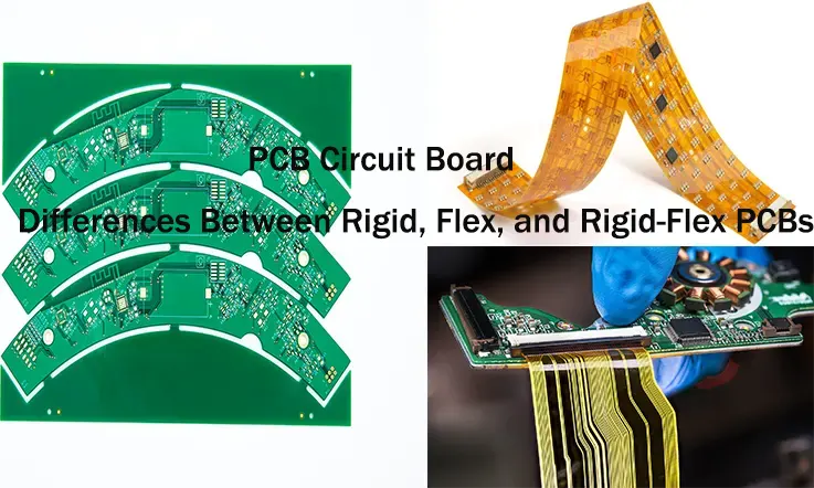
Printed circuit boards are available in rigid, flex, and rigid-flex formats, each designed to meet specific mechanical, electrical, and assembly needs. Rigid PCBs offer structural stability, flex PCBs provide mechanical adaptability, and rigid-flex PCBs combine both features for complex, space-constrained applications.
This article presents a structured technical overview of the differences between these three PCB types. The content examines their materials, mechanical constraints, electrical behavior, manufacturing parameters, and industry-specific applications.
Introduction to PCB Technologies: Rigid, Flex, and Rigid-Flex PCBs
PCBs (Printed Circuit Boards) are used to connect electronic components in a wide range of devices, including smartphones, medical devices, and aerospace systems. The choice of PCB—Rigid, Flex, or Rigid-Flex—determines the form factor, performance, and durability of the product.
In this section, we will examine the differences between these PCB types and their role in electronics manufacturing.
What is a PCB and How It Powers Modern Electronics?
A PCB serves as the base for electrical connections between components like resistors, capacitors, and microchips.
●Structure: PCBs can have multiple layers based on the required complexity.
●Materials: The materials selected, such as fiberglass for rigid boards or polyimide for flexible ones, affect the board’s robustness and heat resistance.
●Manufacturing Process: Fabrication involves processes like etching, drilling, and plating.
PCBs are found in devices ranging from smartphones to industrial systems, enabling them to function smoothly and reliably.
Evolution of Rigid, Flex, and Rigid-Flex PCBs in Manufacturing
The demand for more compact and efficient devices has influenced the development of different PCB types. Initially, Rigid PCBs were used extensively for their reliability in larger devices. Later, Flex PCBs came into play, offering flexibility for smaller, more versatile devices.
●Rigid PCBs: Primarily used in stable electronic devices where flexibility is not needed.
●Flex PCBs: These flexible boards cater to products requiring compact design and the ability to bend or fold.
●Rigid-Flex PCBs: These boards combine the benefits of both rigid and flexible PCBs to meet complex product requirements.
This development highlights how evolving design needs shape the choices for PCB types.
Key Differences Between Rigid, Flex, and Rigid-Flex Circuit Boards
Each type of PCB serves distinct purposes, and understanding these differences helps in selecting the right option for various applications.
●Rigid PCBs: Provide a solid base for components, often used in larger products.
Example: Desktop computers, power systems, automotive electronics.
●Flex PCBs: Offer flexibility, making them good for devices that require compactness and movement.
Example: Wearables, medical devices, and portable gadgets.
●Rigid-Flex PCBs: A hybrid design that incorporates both rigid and flexible sections to offer reliability with flexibility.
Example: Aerospace, military tech, advanced consumer electronics.
The choice between these options affects design, space utilization, and functionality in the final product.
Rigid PCB Technology: Core Features and Applications
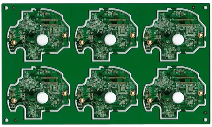
Rigid PCBs are the workhorses of electronic hardware. Their sturdy form, standardized fabrication processes, and compatibility with both through-hole and surface-mount technologies make them a reliable pick for a range of industrial and consumer electronics. From the factory floor to your pocket device, rigid PCBs bring a solid structure that allows for dependable assembly, consistent signal performance, and long-term durability. Now, let’s peel back the layers and dig into the materials, design parameters, and where they’re popping up in real-world applications.
Materials Used in Rigid PCB Manufacturing
Selecting the right material for rigid PCBs sets the tone for thermal endurance, signal behavior, and long-term mechanical integrity. Here’s a breakdown of some go-to materials used across the industry:
FR4 (Flame Retardant Glass Epoxy)-
Most commonly used in 2-layer to multilayer rigid PCBs.
Known for solid insulation resistance and mechanical stability.
Ideal for consumer electronics and general-purpose boards.
Rogers High-Frequency Laminate-
Preferred in RF and microwave designs due to lower dielectric loss.
More stable than FR4 at higher frequencies.
Often used in aerospace communication systems and 5G modules.
Aluminum Core PCBs-
Excellent for heat dissipation; widely used in LED lighting modules.
Combines metal substrate with dielectric insulation for robust performance.
Especially helpful in industrial and automotive applications with high power output.
| Material | Typical Use Case | Thermal Conductivity | Cost Factor |
| FR4 | Consumer Electronics | Low | Low |
| Rogers | High-Frequency RF | Medium to High | Medium to High |
| Aluminum | Power Electronics | High | Medium |
Pro tip: When you’re building for high-speed or high-power systems, don’t skimp on substrate selection — the wrong material could throw a wrench in your whole setup.
Design Considerations for Rigid PCBs
Even the most solid PCB base can go sideways if the layout and stack-up aren’t dialed in. Rigid PCB design isn’t just about slapping on copper and calling it a day — here’s what engineers really focus on:
Layer Stack-Up-
Determines impedance control, crosstalk, and EMI mitigation.
Multilayer boards often use symmetrical stack-ups to minimize warping.
High-layer-count PCBs support better power and ground plane isolation.
Via Types (Through-Hole, Blind, Buried, Microvias)-
Through-hole vias remain standard, but blind and buried vias help shrink form factors.
Microvias are now common in HDI (High Density Interconnect) rigid PCBs.
Via fill and copper plating thickness impact current handling and signal speed.
Signal Integrity-
Rigid boards require well-managed trace width and spacing, especially in high-speed apps.
Impedance mismatch can lead to ringing, reflection, and EMI issues.
Controlled impedance traces, differential pair routing, and ground stitching are common techniques.
Don’t cut corners: Rigid PCB design is where electrical theory meets real-world production — and your product’s performance hinges on getting those specs just right.
Industries Benefiting from Rigid PCBs
Rigid PCBs are the old-school dependable choice for a whole roster of industries. From dashboards to data centers, these boards keep tech rolling in demanding settings.
Automotive Sector-
Used in engine control units, sensor modules, infotainment systems.
Must handle high-temp environments and vibration stress.
Increasing use in EV battery management systems.
Consumer Electronics-
Found in smartphones, laptops, gaming consoles, wearables.
Enables compact layout with solid mechanical support.
Volume manufacturing keeps costs manageable.
Industrial Control and Automation-
Deployed in PLCs, HMI systems, and motor controllers.
Needs robust solder joints and PCB mounting to withstand factory conditions.
Often includes thicker copper layers for high-current traces.
Real-life scenario: A rigid PCB in an industrial motor controller with a 2oz copper layer offers steady current flow and tolerates long-term mechanical stress without flex-related fatigue.
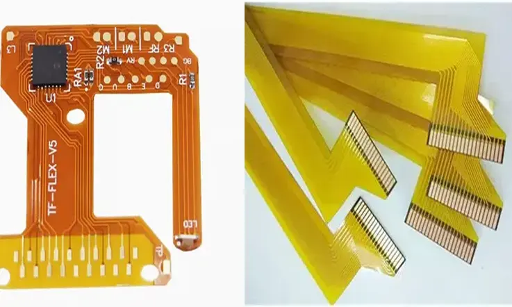
H2: Flex PCB: Flexibility in Design and Manufacturing
As electronics continue to shift toward compact, lightweight, and more mechanically adaptive form factors, flex PCBs have become widely adopted across industries. These circuits allow our engineer designers to create layouts that conform to three-dimensional shapes while maintaining reliable electrical connections. From medical implants to foldable consumer electronics, flexible printed circuit boards offer a structure that supports space-limited and mechanically active environments.
This section explores the major types of flex circuits, essential design parameters, and common use cases across technical sectors.
Types of Flex PCBs
Different applications require different flex configurations. Understanding the construction of each type helps engineers select the right structure for a given electrical and mechanical task.
Single-Sided Flex PCBs-
These circuits contain one conductive copper layer laminated to a flexible polyimide film. They are commonly used in static applications such as digital cameras, printers, or basic display modules. Their streamlined structure supports compact, low-density routing with minimal cost.
Double-Sided Flex PCBs-
With copper layers on both sides of the base film and plated through-holes to connect them, double-sided flex circuits increase routing capabilities. This structure is used in control panels, industrial sensors, and devices where moderate signal complexity is present.
Multilayer Flex PCBs-
When designs demand increased I/O density, power delivery layers, or shielding, multilayer flex circuits are preferred. These are often found in aerospace controls, surgical imaging equipment, and ruggedized military systems. The combination of multiple signal and plane layers on a flexible substrate provides routing freedom without mechanical constraints.
Material Note: The most commonly used base film is polyimide, valued for its high thermal stability and flexibility. Copper thickness and adhesive types vary depending on the required bend cycles and impedance control.
Practical Design Guidelines for Flex PCB Layout
Designing for flex circuitry involves both electrical performance and mechanical longevity. Poor layout can lead to premature failure during repeated movement or thermal cycling.
Bend Radius Control-
Maintain a minimum bend radius of 10x the material thickness for static bends and 20x or more for dynamic applications. This reduces copper fatigue and delamination risk.
Avoid Stress Concentration-
Keep plated-through vias and sharp corners away from active bend zones. Use curved trace routes and tear-drops at pad intersections to spread mechanical stress evenly.
Reinforcement at Transition Areas-
Add FR4 or polyimide stiffeners where the flex section meets connectors or rigid components. Proper support in these regions prevents mechanical peeling and ensures consistent mating in assembly.
Tip: Ground and power planes in dynamic zones should use cross-hatched fills to increase flexibility and reduce metal fatigue.
Application Sectors Utilizing Flex PCBs
Flex circuits are adopted across sectors where size reduction, reliability, and mechanical flexibility are required. Here is a structured overview of typical usage:
| Industry | Application Examples | Why Flex is Applied |
| Medical Electronics | Diagnostic sensors, implants, surgical tools | Withstands sterilization, fits limited spaces |
| Consumer Electronics | Foldable phones, laptops, display modules | Enables thin profiles and tight internal routing |
| Automotive Systems | Driver displays, ADAS sensors, lighting controls | Handles vibration and form-fit enclosure designs |
| Aerospace & Defense | Satellite modules, guided systems, avionics | Lightweight, reliable under mechanical stress |
Each of these use cases shows how flex PCBs provide connectivity in mechanically complex environments while supporting multi-axis folding and bending.
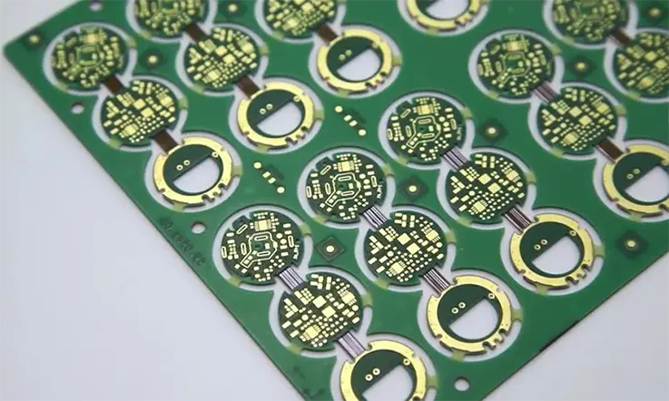
Rigid-Flex PCB: Combining Flexibility and Stability in One Board
As electronic assemblies continue to evolve into more integrated and compact architectures, rigid-flex PCBs have gained wide usage in applications requiring a blend of structural strength and bendable interconnects. These hybrid boards merge the solid platform of rigid PCBs with the pliability of flex circuits, enabling streamlined circuit layouts, minimized connector interfaces, and increased design freedom within tight mechanical envelopes.
What is Rigid-Flex PCB and How It Works?
Rigid-flex PCBs are constructed by laminating flexible polyimide layers with rigid FR4 or similar substrate materials into a unified, interconnected structure. These boards incorporate multiple layers—some of which may be exclusively rigid, exclusively flexible, or a combination of both.
Core technical characteristics:
● Material Integration: Typical builds involve flexible substrates like polyimide combined with rigid materials such as FR4, CEM-3, or high-Tg laminates.
● Layer Interconnect: Through-hole or blind/buried vias link flexible and rigid sections. Adhesiveless copper-clad laminates improve mechanical integrity across transitions.
● Design Flow: The flexible portions act as dynamic or static interconnects, allowing mechanical movement or tight folding within enclosures.
This board type is particularly suited for compact, multi-layered configurations where space constraints make traditional wiring or connectors inefficient.
Advantages of Rigid-Flex PCBs in Complex Systems
Rigid-flex PCBs enable a consolidated PCB architecture that reduces weight, simplifies assembly, and enhances electrical performance in dense or mobile environments.
Key engineering advantages:
●Interconnect Minimization: Fewer solder joints and connectors lower the probability of electrical failures due to mechanical stress or vibration.
●Signal Integrity: Direct routing across rigid and flex layers can minimize impedance discontinuities and parasitic capacitance.
●Compact Assembly: Space savings are achieved by replacing ribbon cables and connectors, and by folding flex sections to accommodate mechanical constraints.
In systems like wearable electronics or handheld instrumentation, this structure can reduce overall volume and streamline the mechanical envelope.
Common Applications of Rigid-Flex PCBs
Rigid-flex circuit boards are frequently chosen for industries that demand dense packaging, stable connectivity, and tolerance to movement or repeated stress.
Main industrial uses include:
●Aerospace: Avionics modules, cockpit electronics, and communication devices where vibration-resistance and space efficiency are high priorities.
●Medical Devices: Surgical instruments, diagnostic imaging systems, and implantable devices that require compact design with consistent performance.
●Military Electronics: Radar systems, communication gear, and unmanned systems where robust structure and mechanical endurance are necessary.
| Application Sector | Typical Product Examples | Design Requirements |
| Aerospace | Navigation controls, sensors | Vibration-resistant, lightweight |
| Medical | Endoscopic probes, imaging tools | Biocompatibility, compact structure |
| Military | Tactical radios, defense control panels | Durability, environmental resilience |
For manufacturers aiming to reduce interconnect complexity while achieving electrical reliability and spatial efficiency, rigid-flex PCB technology presents a viable pathway.
Rigid vs Flex vs Rigid-Flex PCB: Choosing the Right Technology
When designing electronic systems, selecting the right PCB technology—rigid, flexible, or rigid-flex—directly affects assembly processes, product performance, and cost-efficiency. Each PCB type offers distinct advantages based on the application environment, manufacturing limitations, and functional demands of the final product. Understanding the core differences among Rigid, Flex, and Rigid-Flex PCBs helps us make informed decisions aligned with design objectives and real-world use cases.
Performance, Cost, and Design Complexity: A Comparative Analysis
Each of the PCB technologies presents unique trade-offs in terms of performance, design complexity, and production costs. We need to assess these parameters carefully to align the board configuration with application needs and project constraints.
Rigid PCB-
●Performance: Rigid PCBs are stable in their mechanical structure, ideal for applications where vibration resistance is not critical. They support complex multi-layer designs and can handle high-frequency circuits effectively.
●Manufacturing Cost: Rigid PCBs are generally less expensive due to their straightforward manufacturing processes and the availability of standardized materials like FR4. This makes them a cost-effective solution for large-scale production.
●Design Complexity: While the design of Rigid PCBs is relatively simple, involving the use of rigid substrates and standard vias, modifications to the design can be complex and costly, especially when multiple layers are involved.
Flex PCB-
●Performance: Flex PCBs offer better adaptability in dynamic environments, such as wearable technology or applications requiring bending. However, they are not as robust in high-stress environments compared to Rigid PCBs.
●Manufacturing Cost: The initial cost of designing and producing Flex PCBs is higher, primarily due to the use of specialized materials (like polyimide) and more intricate design and fabrication processes. However, the savings in assembly and wiring can offset these costs in certain applications.
●Design Complexity: Flex PCBs require more sophisticated design considerations, such as proper bend radius, flexibility, and routing, making their design more complex than Rigid PCBs. The dynamic nature of Flex PCBs demands higher precision during manufacturing to avoid issues such as cracking or delamination.
Rigid-Flex PCB-
●Performance: Rigid-Flex PCBs combine the best features of both rigid and flexible boards. They are perfect for applications where the flexibility of a Flex PCB is required in certain areas, but rigid sections are necessary for components that must be securely mounted. This allows for compact, lightweight designs while maintaining a high level of reliability.
●Manufacturing Cost: Rigid-Flex PCBs are generally more expensive due to the complexity of their design and manufacturing processes, involving both rigid and flexible materials. The cost can increase with the number of layers and transitions required.
●Design Complexity: Designing Rigid-Flex PCBs is the most complex of the three. We must carefully plan the transitions between flexible and rigid sections, ensuring that the materials bond correctly and that there is no interference between the flexible and rigid areas.
Use Cases and Applications: What to Choose for Your Product
Each PCB type has been developed to suit specific design requirements and operational environments. Understanding the distinct applications for Rigid, Flex, and Rigid-Flex PCBs allows us to select the best option based on the product’s functionality, size constraints, and durability requirements.
Rigid PCB Applications-
●Consumer Electronics: Rigid PCBs are commonly used in devices like smartphones, laptops, and home appliances. The structure’s durability and cost-effectiveness make it suitable for products that do not require flexible components.
●Automotive Electronics: Rigid PCBs are frequently used in control systems, navigation systems, and sensors within vehicles. Their stable structure and thermal endurance allow them to perform consistently under the mechanical and environmental conditions found in automotive applications.
●Industrial Equipment: Industrial control systems, power supplies, and robotics benefit from the robustness and versatility of Rigid PCBs, which can handle high-power loads and multi-functional components.
Flex PCB Applications-
●Wearable Technology: Flex PCBs are perfect for wearables, such as fitness trackers and smartwatches, due to their ability to conform to curved surfaces and operate under constant movement.
●Medical Devices: For medical instruments that require flexible, lightweight, and compact designs, such as heart monitors or implantable devices, Flex PCBs are ideal. They can be integrated into small spaces and bend without compromising performance.
●Consumer Electronics:In devices with limited internal space and high mobility demands, such as foldable phones or wireless earphones, Flex PCBs support compact layouts by enabling tight bending and adaptable geometry within the enclosure.
Rigid-Flex PCB Applications-
●Aerospace: Rigid-Flex PCBs are used in aerospace applications where both flexibility and rigidity are required in a single system, such as in flight control systems or satellite communication devices. The ruggedness and lightweight nature of Rigid-Flex PCBs make them better for harsh environments.
●Medical Devices: In advanced medical technologies like imaging systems or wearable diagnostic tools, Rigid-Flex PCBs combine compactness with the necessary rigidity for sensitive components.
●Military Electronics: Rigid-Flex PCBs are well-suited for military-grade devices that require high reliability, space optimization, and resistance to extreme conditions, such as military communication systems and weaponry control panels.
Advantages and Disadvantages of Rigid, Flex, and Rigid-Flex Designs
Choosing the right PCB technology requires a clear understanding of the specific advantages and trade-offs for each type.
Rigid PCB Advantages and Disadvantages-
Advantages:
●Well-suited for high-volume, cost-sensitive applications.
●Offers excellent mechanical stability for components that need to be mounted securely.
●Widely compatible with automated assembly processes.
Disadvantages:
●Lack of flexibility makes it unsuitable for applications requiring dynamic movement or deformation.
●Requires more space and connectors for complex designs.
Flex PCB Advantages and Disadvantages-
Advantages:
●Provides high flexibility, ideal for compact spaces and dynamic applications.
●Reduces the need for wiring and connectors, leading to smaller, lighter products.
●Can be bent to fit various shapes, making it perfect for curved surfaces.
Disadvantages:
●Higher production costs due to the specialized materials and manufacturing techniques.
●Greater risk of damage during handling, especially at bending points.
Rigid-Flex PCB Advantages and Disadvantages-
Advantages:
●Combines the advantages of both rigid and flexible PCBs, allowing for highly compact and integrated designs.
●Reduces the need for separate connectors and cables, increasing system reliability.
●Reliable for products that need to fit into tight spaces while maintaining structural integrity.
Disadvantages:
●The most expensive PCB option due to the complex manufacturing process.
●Design and fabrication require a longer lead time and more precise engineering.
Materials in Rigid, Flex, and Rigid-Flex PCBs
The choice of base materials in PCB manufacturing heavily influences product reliability, thermal performance, and electrical behavior across different environments. For rigid, flex, and rigid-flex PCBs, substrate selection isn’t just a design checkbox—it’s a foundational step that shapes how the board handles real-world use in industries like aerospace, defense, medical systems, and industrial automation. Below, we explore how specific materials meet the physical and mechanical demands of diverse PCB formats.
Choosing the Right Substrate for Rigid and Flex PCBs
Selecting substrates for rigid and flex PCBs involves weighing trade-offs in dielectric strength, thermal conductivity, flexibility, and cost efficiency. For rigid PCBs, FR-4 epoxy laminate remains the standard due to its stable electrical insulation properties and mechanical strength. When high-frequency signal transmission is required—particularly in RF and microwave applications—Rogers laminates such as RO4003C and RO4350B offer more controlled impedance and lower dielectric loss than FR-4.
Flex PCBs typically use polyimide film substrates such as Kapton or Apical due to their capacity to endure repeated mechanical bending and elevated thermal exposure. These materials provide stable dimensional characteristics and maintain electrical and mechanical reliability during prolonged thermal cycling, which supports consistent function in dynamic-flex applications like consumer wearables and medical probes.
Key substrate categories:
●FR-4 (Rigid): Glass-reinforced epoxy laminate; cost-effective, widely used.
●Rogers (Rigid): PTFE and ceramic-filled laminates; used for RF/microwave circuits.
●Polyimide (Flex): Thin, heat-resistant base for dynamic flex applications.
Common substrate comparison:
| Material | Dielectric Constant (Dk) | Loss Tangent | Flexibility | Thermal Stability (°C) |
| FR-4 | 4.50 | 0.0200 | Low | 130 |
| Rogers RO4003C | 3.38 | 0.0027 | Low | 260 |
| Rogers RO4350B | 3.48 | 0.0037 | Low | 260 |
| Polyimide (Kapton) | 3.50 | 0.0020 | High | 400 |
| Polyimide (Apical) | 3.40 | 0.0020 | High | 400 |
Material decisions should align with the end-use case, mechanical stress level, and thermal budget of the final assembly.
Thermal Management and Material Selection in Rigid-Flex
Rigid-flex PCBs combine rigid and flex layers in one unified structure. The thermal dynamics across rigid and flex zones require careful coordination, especially in high-density interconnect (HDI) designs and multi-layer stacks. In rigid zones, aluminum or copper-core substrates can improve thermal dissipation when placed near high-power ICs or power converters. These are often paired with thermally conductive prepregs and low-CTE laminates to maintain layer stability during solder reflow.
In flex zones, maintaining material pliability while managing localized heating from flexing traces is a balancing act. High-temperature polyimide with low outgassing characteristics is typically used here, especially in aerospace-grade designs.
Design recommendations:
●Use low-Z-axis expansion laminates to prevent via failure.
●Apply thermal relief pads around plated through-holes (PTHs).
●Combine thermally conductive adhesives with polyimide layers for stability.
Typical thermal material characteristics:
| Material | Thermal Conductivity (W/m·K) | CTE (ppm/°C) | Application Zone | Notes |
| Aluminum Core | 200.0 | 23 | Rigid | Applied under heat-generating components |
| Copper Core | 400.0 | 17 | Rigid | Used for uniform thermal spreading |
| Thermal Prepreg | 1.5 | 70 | Rigid | Supports multi-layer lamination stability |
| Polyimide | 0.2 | 20 | Flex | Maintains flexibility at high temperatures |
| Thermal Adhesive | 2.0 | 60 | Interface | Strengthens bonding in flex-rigid interfaces |
High-Thermal Conductivity Materials for Flex and Rigid-Flex Applications
In demanding sectors like automotive radar systems or medical imaging equipment, where thermal stress is a design constraint, selecting materials with high thermal conductivity is a must. For flex circuits, ceramic-filled polyimide films or thermally enhanced adhesives can be applied to move heat efficiently across tight geometries.
For rigid-flex builds, IMS (Insulated Metal Substrate) cores may be integrated into the rigid regions to improve thermal transfer beneath surface-mount power components. These systems often combine polyimide films, copper foils, and thermally conductive prepregs to maintain system stability during load fluctuations.
Examples of high-thermal performance materials:
●Thermagon T-preg series
●Ceramic-filled epoxy hybrids
●Aluminum-backed polyimide laminates
To reduce failure rates in harsh environments, the synergy between thermal management and material layering cannot be overlooked during design and lamination.
Examples of thermally engineered materials:
| Material | Thermal Conductivity (W/m·K) | Typical Use | Structure | Max Operating Temp (°C) |
| Thermagon T-preg | 3.00 | Power electronics | Prepreg | 200 |
| RT/duroid 6035HTC | 1.44 | RF Power Circuits | Laminated PTFE | 200 |
| Ceramic Epoxy Hybrid | 2.50 | Medical Imaging | Resin Composite | 180 |
| Aluminum-Backed Polyimide | 1.00 | Automotive Flex Circuits | Laminated Film | 150 |
Material selection is not just about conductivity—it also affects assembly temperature tolerance, bonding compatibility, and dimensional control throughout the product lifecycle.
Industry Standards and Best Practices for Rigid, Flex, and Rigid-Flex PCBs
In circuit board manufacturing, consistent adherence to industry-defined standards helps ensure predictable performance, manufacturing reliability, and end-product compatibility. For rigid PCBs, flex PCBs, and rigid-flex designs, international guidelines—such as those provided by IPC—form the basis for fabrication and inspection across multiple sectors including aerospace, consumer electronics, medical technology, and military hardware.
Each PCB type—rigid, flex, and rigid-flex—requires distinct process controls, materials handling, and inspection routines. These boards are subject to environmental stress, mechanical flex, and miniaturization demands that push our engineers and production teams to closely align with standardized design and quality benchmarks.
IPC Standards for Rigid, Flex, and Rigid-Flex PCBs
The IPC (Association Connecting Electronics Industries) issues a wide range of specifications that guide layout, fabrication, testing, and acceptance.
Common IPC documents applied across board types:
●IPC-2221/2223: These documents define generic design requirements and flex-specific design guidelines, respectively. IPC-2223, for instance, provides detailed insight on bend radius, coverlay placement, and conductor routing in flex and rigid-flex layouts.
●IPC-6012 & IPC-6013: IPC-6012 addresses performance requirements for rigid PCBs, while IPC-6013 covers the flex and rigid-flex categories. Both standards dictate visual inspection criteria, dielectric integrity, and interconnect testing.
●IPC-A-600 & IPC-A-610: Visual acceptability criteria, including laminate voids, conductor spacing, and hole quality, are governed under these visual inspection guidelines. IPC-A-610 is especially useful for contract manufacturers and assembly houses evaluating product quality from incoming inspection through final assembly.
Manufacturers working across consumer, aerospace, or defense sectors often adopt Class 2 or Class 3 designations from IPC, depending on how much reliability and extended performance the product must deliver. Class 3 compliance (high-reliability electronics) is common in avionics and surgical instrumentation, where failures are not easily tolerated.
Design Guidelines for Signal Integrity and Impedance Control
Effective signal integrity starts with intentional stack-up planning, particularly when using mixed rigid-flex configurations. Flex layers are typically thinner, making them more susceptible to impedance drift, dielectric inconsistencies, or cross-talk if not designed correctly.
Areas manufacturers and layout engineers monitor:
●Controlled Impedance: Impedance is calculated based on conductor width, spacing, and dielectric thickness. Rigid-flex PCBs often require tight trace width tolerances and uniform prepreg material properties, especially in differential signal pairs.
●Return Path Continuity: Maintaining a low-inductance ground path, particularly in flex-to-rigid transitions, is necessary to reduce electromagnetic interference. Therefore, some designers often implement stitched ground planes or shielding layers on flex segments.
●Bend Area Considerations: Traces are routed orthogonally across bend areas to reduce signal reflection or fatigue cracking. High-speed lines should avoid sharp corners or transitions near bends.
For RF, medical, and telecom designs, simulation tools such as Ansys SIwave or Keysight ADS are used in the design phase to validate signal paths before prototyping. Maintaining signal behavior across rigid and flex sections can reduce time-consuming rework during fabrication.
Quality Control and Testing Methods for Rigid-Flex and Flex PCBs
Quality control in rigid-flex and flex PCB production goes far beyond visual inspection. These circuits must meet stringent mechanical and electrical benchmarks while also withstanding bending and vibration during assembly or operation.
Testing methodologies include:
●Automated Optical Inspection (AOI): Used post-etch and post-solder to catch shorts, opens, or conductor defects.
●Flying Probe and Electrical Testing: Ensures open/short resistance checks across multiple layers, especially important where rigid and flex materials interface.
●Flex Cycle Testing: Rigid-flex PCBs often undergo flex life testing, where the flex region is repeatedly bent to confirm durability under dynamic use. This is common in automotive and medical products with movable joints.
●X-ray and Microsection Analysis: Confirms plated through-hole (PTH) integrity, layer registration, and resin flow characteristics. Especially useful for high-layer-count or hybrid rigid-flex assemblies.
In addition, traceability systems such as QR-coded boards, material lot tracking, and IPC compliance documentation are standard practices among OEM suppliers serving aerospace, defense, and regulated industries. These ensure transparency and accountability throughout the fabrication lifecycle.
How Selecting the Optimal PCB for Your Application?
As electronic product designs become more specialized across sectors like automotive, aerospace, and medical technology, selecting a suitable PCB technology—rigid, flex, or rigid-flex—requires a thorough understanding of electrical performance, mechanical constraints, material compatibility, and manufacturing process alignment. Each PCB structure supports specific mechanical and electronic functions based on use-case environments, signal requirements, and design geometry. The sections below outline the practical aspects of decision-making, fabrication partnership, and industry trends, with a focus on actionable parameters and performance-based engineering logic.
Rigid, Flex, and Rigid-Flex PCBs: Which One to Choose?
Selecting between rigid, flex, and rigid-flex PCBs depends on a blend of design mechanics, thermal behavior, and expected lifecycle stresses. Consider the following when evaluating:
Mechanical Requirements-
●Rigid PCBs offer strong dimensional stability and are best suited for static assemblies. Flex circuits support movement and conformability, while rigid-flex bridges rigid and flexible segments for compact, folding designs.
Environmental Conditions-
●Flex and rigid-flex PCBs tolerate vibration and flex cycles better due to their polyimide-based substrates. Applications involving wearable electronics, folding devices, or aerospace sensor arms often leverage these designs.
Signal Routing and Density-
●Rigid and rigid-flex structures support higher layer counts and controlled impedance better than single-layer flex boards. Use these for dense digital and mixed-signal routing.
Manufacturing Considerations-
●Rigid PCBs generally involve fewer process steps, making them suitable for high-yield production. Flex and rigid-flex require precision lamination and drilling alignment, particularly during ZIF connector zone preparation and layer transition fabrication.
For example, in automotive rear-view camera systems, rigid-flex PCBs are commonly used to combine a compact control module with a flexible tail for positioning the camera housing.
Partnering with a Trusted PCB Manufacturer for Optimal Results
Working with a reliable PCB fabrication partner brings process stability and technical alignment from prototyping through production. Engineering teams should evaluate partners based on:
Material Sourcing Capabilities-
●The manufacturer should support a range of UL-rated laminates, polyimide films, and high-temperature adhesives required for thermal resilience and dielectric control.
Certification and Compliance-
●IPC Class 2 and Class 3 compliance, UL certifications, and ITAR registration (for defense and aerospace sectors) reflect adherence to quality frameworks relevant to specific sectors.
DFM and Stack-Up Simulation Services-
●Experienced partners provide Design for Manufacturability (DFM) reviews, impedance modeling, and signal integrity validation prior to CAM programming. This is particularly valuable in rigid-flex designs with buried or staggered vias across rigid-to-flex transitions.
Volume Capabilities and Lead Times-
●For consumer product timelines, ensure the partner can accommodate both prototype runs and full production with consistent trace widths, dielectric tolerances, and soldermask registration.
Before moving into fabrication, request detailed build-up stackups, via fill options, and thermal stress simulation results to align with your electrical and mechanical objectives.
Future Trends in PCB Manufacturing and Design
PCB technology is evolving in response to materials research, assembly automation, and high-frequency application requirements. Forward-looking considerations include:
Embedded Component Integration-
●To reduce height and enable signal integrity improvements, embedded passive elements (resistors, capacitors) are being designed directly into rigid or flex substrates.
Advanced Material Usage-
●Low-Dk, low-loss laminates such as Rogers 3000 series are increasingly used in RF systems, while copper-invar-copper cores support dimensional control in HDI multilayer constructions.
Miniaturization and Multi-Axis Folding-
●Next-gen flex and rigid-flex designs support bendable modules with curved traces, commonly used in wearables, endoscopy tools, and compact radar systems.
Laser Drilling and Semi-Additive Processing-
●Fine-line processing is shifting toward mSAP (modified semi-additive process) with laser via drilling and sputtering methods for sub-50 µm trace/space applications in 5G infrastructure and IC substrates.
FAQ: Rigid, Flex, and Rigid-Flex PCBs
1.Are Flex PCBs suitable for high-speed signal transmission?
Yes, with proper impedance control and trace design, flex circuits can support high-speed digital and RF signals.
2.What’s the typical bend radius for a Flex PCB?
A general guideline is a minimum bend radius of 6 to 10 times the thickness of the flex material.
3.Are there limitations on the number of layers in a Flex PCB?
While flex boards can support multiple layers, design complexity and manufacturing cost increase with layer count.
4.How are Rigid-Flex PCBs assembled?
They typically undergo a combination of SMT and through-hole assembly processes, depending on the component layout.
5.What’s the standard copper thickness used in Flex PCBs?
Common thicknesses are 0.5 oz, 1 oz, or 2 oz per square foot, depending on current requirements and bend performance.
6.Can Rigid PCBs be partially flexible?
No, unless integrated as part of a rigid-flex design. Rigid PCBs do not allow mechanical flexing.